


Interrupt Control Unit
8-32
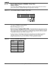
8.4.5 Interrupt Request Register (REQST, Offset 2Eh)
(Slave Mode)
The internal interrupt sources have interrupt request bits inside the interrupt controller. A
read from this register yields the status of these bits. The Interrupt Request Register is a
read-only register. The format of the Interrupt Request Register is shown in Figure 8-21.
For internal interrupts (D1, D0, TMR2, TMR1, and TMR0), the corresponding bit is set to
1 when the device requests an interrupt. The bit is reset during the internally generated
interrupt acknowledge.
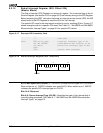
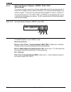
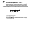
Figure 8-21 Interrupt Request Register (REQST, offset 2Eh)
The REQST Register is set to 0000h on reset.
Bits 15–6: Reserved
Bits 5–4: Timer 2/Timer 1 Interrupt Request (TMR2–TMR1)—When set to 1, these bits
indicate the state of any interrupt requests from the associated timer.
Bits 3–2: DMA Channel Interrupt Request (D1–D0)—When set to 1, D1–D0 indicate that
the corresponding DMA channel has an interrupt pending.
Bit 1: Reserved
Bit 0: Timer 0 Interrupt Request (TMR0)—When set to 1, this bit indicates the state of
an interrupt request from Timer 0.
15
70
Reserved
D0
D1
TMR1
TMR2
Res
TMR0