


System Overview
3-1
CHAPTER
3
SYSTEM OVERVIEW
This chapter contains descriptions of the Am186ER and Am188ER microcontroller pins,
the bus interface unit, the clock and power management unit, and the power-save operation.
3.1 PIN DESCRIPTIONS
Pin Terminology
The following terms are used to describe the pins:
Input—An input-only pin.
Output—An output-only pin.
Input/Output—A pin that can be either input or output.
Synchronous—Synchronous inputs must meet setup and hold times in relation to
CLKOUTA. Synchronous outputs are synchronous to CLKOUTA.
Asynchronous—Inputs or outputs that are asynchronous to CLKOUTA.
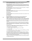
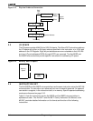
A19–A0 Address Bus (output, three-state, synchronous)
The A19–A0 pins supply nonmultiplexed memory or I/O addresses to
the system one-half of a CLKOUTA period earlier than the multiplexed
address and data bus (AD15–AD0 on the Am186ER microcontroller or
AO15–AO8 and AD7–AD0 on the Am188ER microcontroller). During a
bus hold or reset condition, the address bus is in a high-impedance
state.
AD7–AD0 Address and Data Bus
(input/output, three-state, synchronous, level-sensitive)
These time-multiplexed pins supply partial memory or I/O addresses,
as well as data, to the system. AD7–AD0 supply the low-order 8 bits of
an address to the system during the first period of a bus cycle (t
1
). On
a write, these pins supply data to the system during the remaining
periods of that cycle (t
2
, t
3
, and t
4
). On a read, these pins latch data at
the end of t
3
.
Also, if S0
/SREN (show read enable) was pulled Low during reset or if
the SR bit is set in the Internal Memory Chip Select (IMCS) Register,
these pins supply the data read from internal memory during t
3
and t
4
.
On the Am186ER microcontroller, AD7–AD0 combine with AD15–AD8
to form a complete multiplexed address and 16-bit data bus.
On the Am188ER microcontroller, AD7–AD0 combine with AO15–AO8
to form a complete multiplexed address bus while AD7–AD0 is the 8-bit
data bus.