


Programmable I/O Pins
13-4
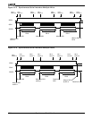
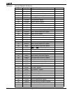
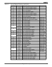
13.3 PIO DIRECTION REGISTERS
Each PIO is individually programmed as an input or output by a bit in one of the PIO Direction
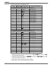
registers (see Figure 13-4 and Figure 13-5). Table 13-2, “PIO Mode and PIO Direction
Settings,” on page 3 shows the values that the PIO mode bits and the PIO direction bits
can encode. The column titled
Power-On Reset State
in Table 13-1 lists the reset default values
for the PIOs. Bits in the PIO Direction registers have the same correspondence to pins as bits
in the PIO Mode registers.
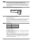
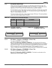
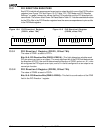
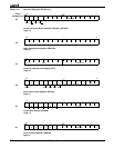
13.3.1 PIO Direction 1 Register (PDIR1, Offset 78h)
The value of PDIR1 at reset is FFFFh.
Bits 15–0: PIO Direction Bits (PDIR31–PDIR16)—This field determines whether each
PIO pin acts as an input or an output. The most significant bit of the PDIR field determines
the direction of PIO31, the next bit determines the direction of PIO30, and so on. A 1 in the
bit configures the PIO signal as an input, and a 0 in the bit configures it as an output or as
normal pin function.
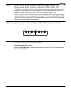
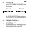
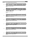
13.3.2 PIO Direction 0 Register (PDIR0, Offset 72h)
The value of PDIR0 at reset is FC0Fh.
Bits 15–0: PIO Direction Bits (PDIR15–PDIR0)—This field is a continuation of the PDIR
field in the PIO Direction 1 register.
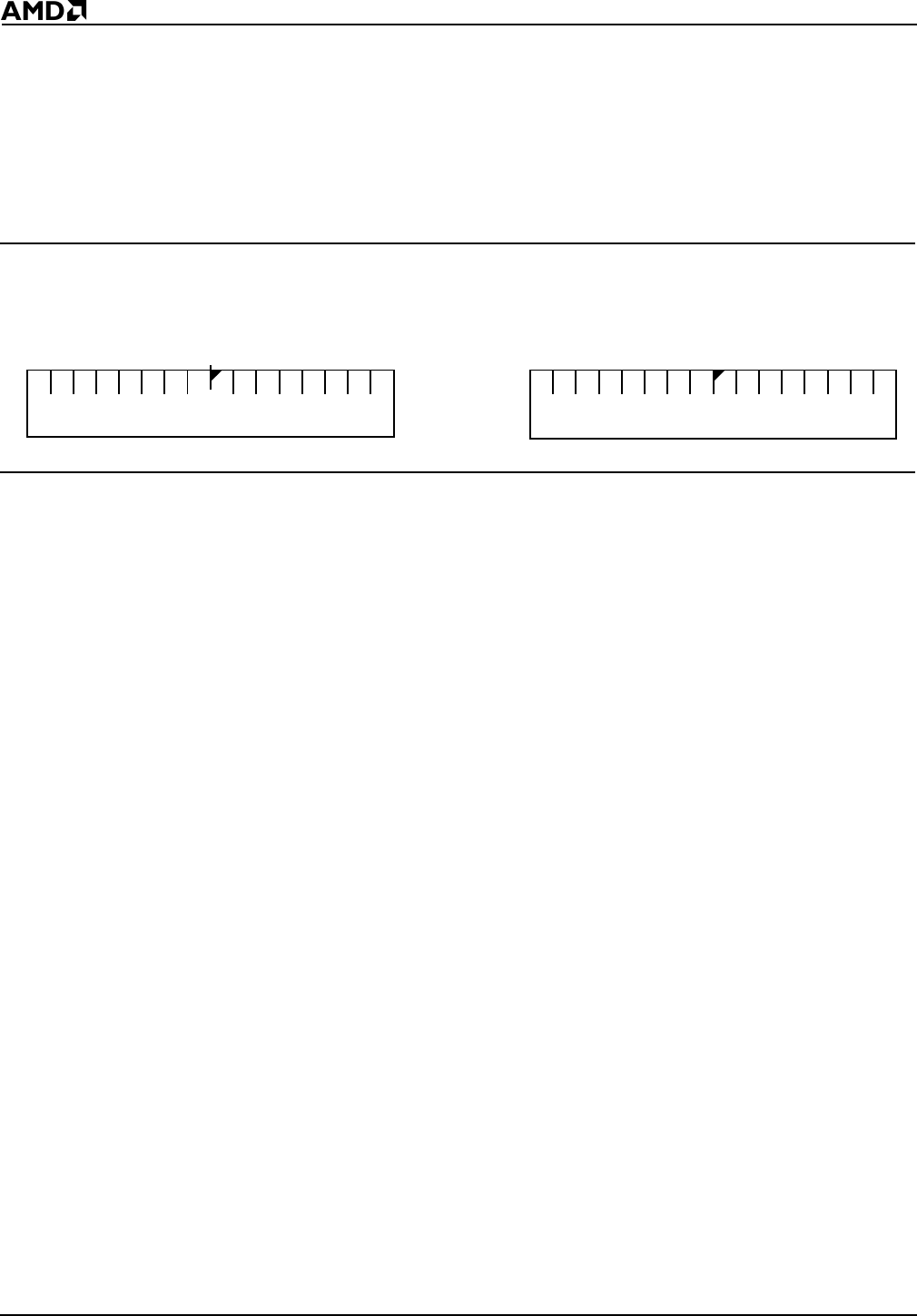
15 7 0
PDIR (31–16)
Figure 13-4 PIO Direction 1 Register
(PDIR1, offset 78h)
15 7 0
PDIR (15–0)
Figure 13-5 PIO Direction 0 Register
(PDIR0, offset 72h)