


Interrupt Control Unit
8-25
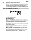
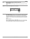
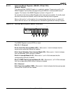
8.3.11 Interrupt Mask Register (IMASK, Offset 28h)
(Master Mode)
The Interrupt Mask (IMASK) Register is a read/write register. Programming a bit in the
IMASK Register has the effect of programming the MSK bit in the associated control
register. The format of the IMASK Register is shown in Figure 8-14.
Do not write to the Interrupt Mask Register while interrupts are enabled. To modify mask
bits while interrupts are enabled, use the individual interrupt control registers.
When a bit is set to 1 in this register, the corresponding interrupt source is masked off.
When the bit is set to 0, the interrupt source is enabled to generate an interrupt request.
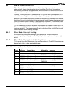
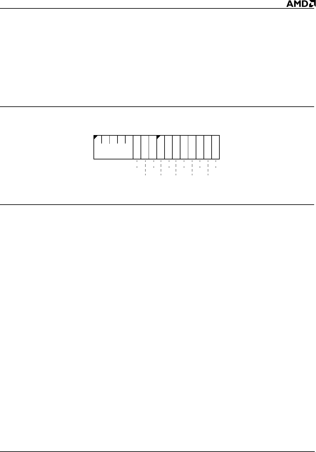
Figure 8-14 Interrupt Mask Register (IMASK, offset 28h)
The IMASK Register is set to 07FDh on reset.
Bits 15–11: Reserved
Bit 10: Serial Port Interrupt Mask (SPI)— When set to 1, this bit indicates that the
asynchronous serial port interrupt is masked.
Bit 9: Virtual Watchdog Timer Interrupt Mask (WD)—When set to 1, this bit indicates
that the Watchdog Timer interrupt is masked.
Bits 8–4: Interrupt Mask (I4–I0)—When set to 1, an I4–I0 bit indicates that the
corresponding interrupt is masked.
Bits 3–2: DMA Channel Interrupt Masks (D1–D0)—When set to 1, a D1–D0 bit indicates
that the corresponding DMA channel interrupt is masked.
Bit 1: Reserved
Bit 0: Timer Interrupt Mask (TMR)—When set to 1, this bit indicates that interrupt requests
from the timer control unit are masked.
15
70
Reserved
Res
TMR
D0
D1
I0
I1
I2
I3
I4
WD
SPI