


Interrupt Control Unit
8-19
8.3.5 Watchdog Timer Interrupt Control Register (WDCON, Offset 42h)
(Master Mode)
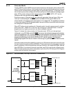
The watchdog timer is implemented by connecting the TMROUT1 output to an additional
internal interrupt to create the watchdog timer interrupt. This interrupt is assigned to interrupt
type 11h. The control register format is shown in Figure 8-8.
The systems programmer should program the timer (see section 9.2.2 on page 9-3) and
then program the interrupt control register.
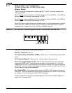
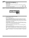
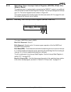
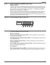
Figure 8-8 Watchdog Timer Interrupt Control Register (WDCON, offset 42h)
The value of WDCON at reset is 000Fh.
Bits 15–5: Reserved—Set to 0.
Bit 4: Reserved—
Must
be set to 0 to ensure proper operation of the Am186ER and
Am188ER microcontrollers.
Bit 3: Mask (MSK)—This bit determines whether the watchdog timer can cause an interrupt.
A 1 in this bit masks this interrupt source, preventing the watchdog timer from causing an
interrupt. A 0 in this bit enables watchdog timer interrupts.
This bit is duplicated in the Interrupt Mask Register. See the Interrupt Mask Register in
section 8.3.11 on page 8-25.
Bits 2–0: Priority (PR)—This field determines the priority of the watchdog timer relative
to the other interrupt signals, as shown in Table 8-3, “Priority Level,” on page 8-15.
15
70
Reserved
MSK
PR2
PR1
PR0