


DMA Controller
10-2
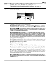
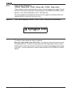
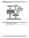
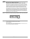
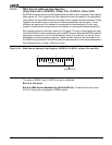
Figure 10-1 DMA Unit Block Diagram
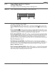
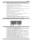
10.3 PROGRAMMABLE DMA REGISTERS
The sections on the following pages describe the control registers that are used to configure
and operate the two DMA channels.
Source Address Ch. 1
Source Address Ch. 0
20-bit Adder/Subtractor
DMA
Control
Logic
Request
Selection
Logic
Adder Control
Logic
20
20
Channel Control Register 1
Channel Control Register 0
16
DRQ1
DRQ0
Internal Address/Data Bus
Timer Request
Interrupt
Request
Transfer Counter Ch. 1
Destination Address Ch. 1
Destination Address Ch. 0
Transfer Counter Ch. 0