


Programmable I/O Pins
13-2
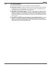
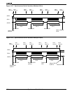
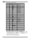
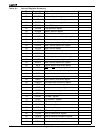
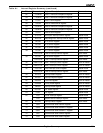
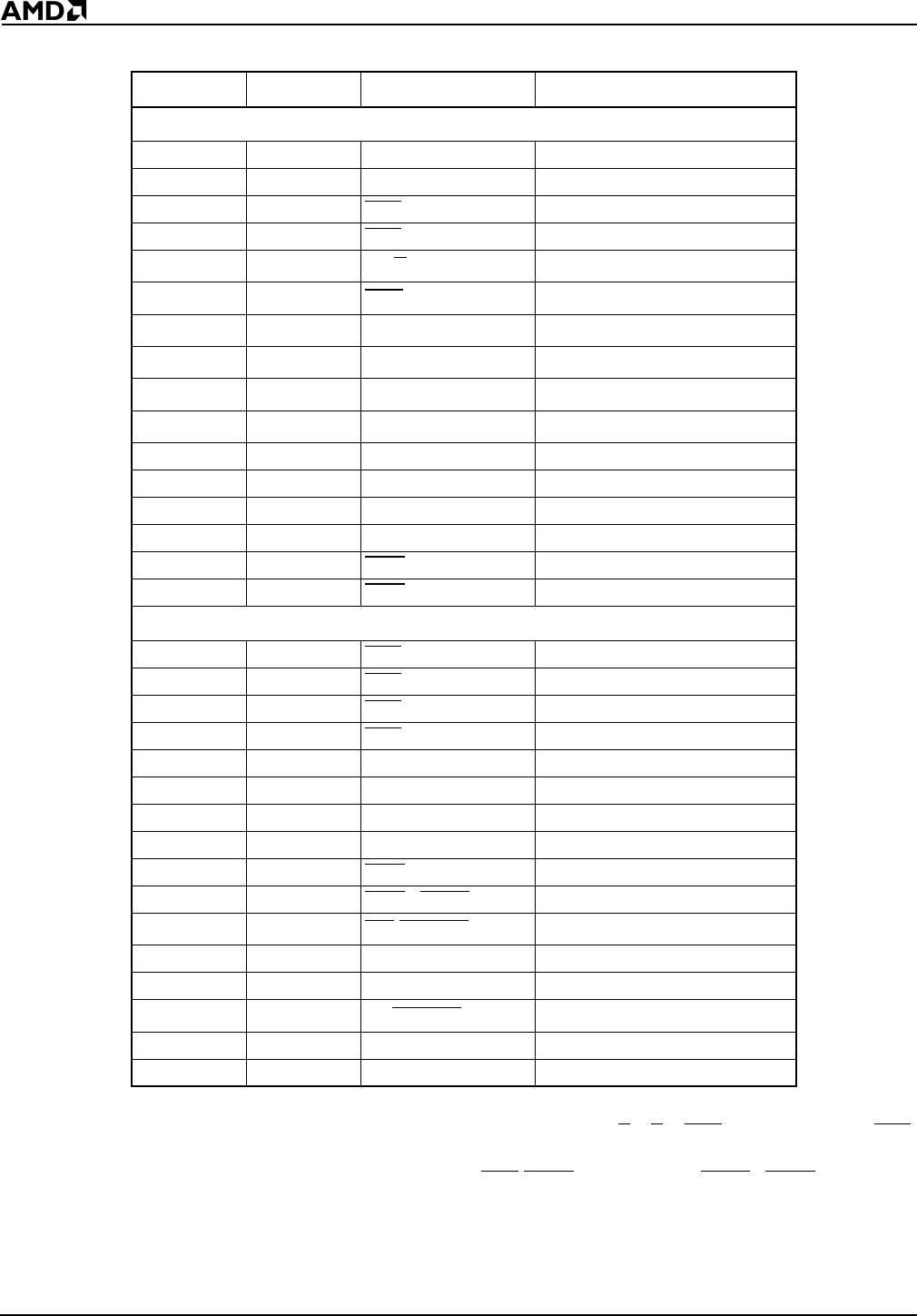
Table 13-1 PIO Pin Assignments and Register Bits
Notes:
1. These pins are used by emulators. (Emulators also use S
2–S0, RES, NMI, CLKOUTA, BHE,
ALE, AD15–AD0, and A16–A0.)
2. These pins revert to normal operation if BHE
/ADEN (Am186ER) or RFSH2/ADEN (Am188ER)
is held Low during power-on reset.
3. When used as a PIO, input with pullup option available.
4. When used as a PIO, input with pulldown option available.
PIO No. Register Bit Associated Pin Power-On Reset Status
“0” Registers (PIOMODE0, 70h; PDIR0, 72h; PDATA0, 74h)
0 0 TMRIN1 Input with pullup
1 1 TMROUT1 Input with pulldown
22PCS
6/A2 Input with pullup
33PCS
5/A1 Input with pullup
44DT/R
Normal operation
(3)
55DEN
Normal operation
(3)
66SRDY
Normal operation
(4)
7
(1)
7A17
Normal operation
(3)
8
(1)
8A18
Normal operation
(3)
9
(1)
9A19
Normal operation
(3)
10 10 TMROUT0 Input with pulldown
11 11 TMRIN0 Input with pullup
12 12 DRQ0 Input with pullup
13 13 DRQ1 Input with pullup
14 14 MCS
0 Input with pullup
15 15 MCS
1 Input with pullup
“1” Registers (PIOMODE1, 76h; PDIR0, 78h; PDATA0, 7Ah)
16 0 PCS
0 Input with pullup
17 1 PCS
1 Input with pullup
18 2 PCS
2 Input with pullup
19 3 PCS
3 Input with pullup
20 4 SCLK Input with pullup
21 5 SDATA Input with pullup
22 6 SDEN0 Input with pulldown
23 7 SDEN1 Input with pulldown
24 8 MCS
2 Input with pullup
25 9 MCS
3/RFSH Input with pullup
26
(1,2)
10 UZI/CLKSEL2 Input with pullup
27 11 TXD Input with pullup
28 12 RXD Input with pullup
29
(1,2)
13 S6/CLKSEL1 Input with pullup
30 14 INT4 Input with pullup
31 15 INT2 Input with pullup