


System Overview
3-9
Note: Unlike the UCS and LCS chip selects, the PCS outputs assert
with the multiplexed AD address bus. Note also that each peripheral
chip select asserts over a 256-byte address range, which is twice the
address range covered by peripheral chip selects in the original 80C186
and 80C188 microcontrollers.
A2—When the EX bit in the MCS
and PCS Auxiliary Register is 0, this
pin supplies an internally latched address bit 2 to the system. During a
bus hold condition, A2 retains its previously latched value.
PIO31–PIO0 (Shared)
Programmable I/O Pins (input/output, asynchronous, open-drain)
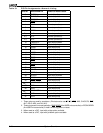
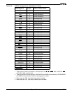
The Am186ER and Am188ER microcontrollers provide 32 individually
programmable I/O pins. The pins that are multiplexed with PIO31–PIO0
are listed in Table 3-1 and Table 3-2. Each PIO can be programmed
with the following attributes: PIO function (enabled/disabled), direction
(input/output), and weak pullup or pulldown. See Chapter 12 for the PIO
control registers.
On the Am186ER and Am 188ER microcontrollers, the internal pullup
resistor has a value of approximately 100 kohms. The internal pulldown
resistor has a value of approximately 100 kohms.
After power-on reset, the PIO pins default to various configurations. The
column titled
Power-On Reset Status
in Table 3-1 and Table 3-2 lists
the defaults for the PIOs. The system initialization code must
reconfigure any PIOs as required.
If PIO29 (S6/CLKSEL
1) is to be used in input mode, the input device
must not drive PIO29 Low during power-on reset. The pin defaults to a
PIO input with pullup, so it does not need to be driven High externally.
The A19–A17 address pins default to normal operation on power-on
reset, allowing the processor to correctly begin fetching instructions at
the boot address FFFF0h. The DT/R
, DEN, and SRDY pins also default
to normal operation on power-on reset.