


Interrupt Control Unit
8-30
8.4.3 Timer and DMA Interrupt Control Registers
(T0INTCON, Offset 32h, T1INTCON, Offset 38h, T2INTCON, Offset
3Ah, DMA0CON, Offset 34h, DMA1CON, Offset 36h)
(Slave Mode)
In Slave mode, there are three separate registers for the three timers. In Master mode, all
three timers are masked and prioritized in one register, TCUCON.
In Slave mode, the two DMA control registers retain their functionality and addressing from
Master mode.
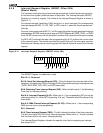
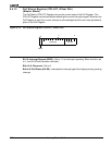
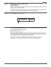
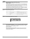
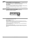
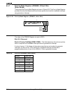
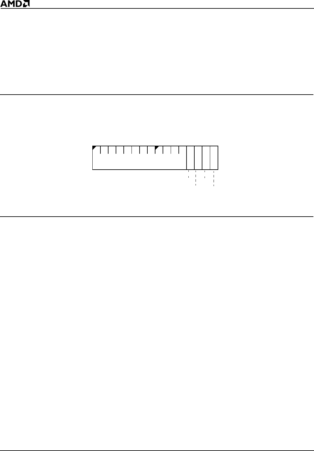
Figure 8-19 Timer and DMA Interrupt Control Registers
(T0INTCON, T1INTCON, T2INTCON, DMA0CON, DMA1CON,
offsets 32h, 38h, 3Ah, 34h, and 36h)
These registers are set to 000Fh on reset.
Bits 15–4: Reserved—Set to 0.
Bit 3: Mask (MSK)—This bit determines whether the interrupt source can cause an
interrupt. A 1 in this bit masks the interrupt source, preventing the source from causing an
interrupt. A 0 in this bit enables interrupts from the source.
This bit is duplicated in the Interrupt Mask Register. See the Interrupt Mask Register in
section 8.4.8 on page 8-35.
Bits 2–0: Priority Level (PR2–PR0)—This field determines the priority of the interrupt
source relative to the other interrupt signals, as shown in Table 8-3, “Priority Level,” on
page 8-15.
15
70
PR2
PR1
PR0
MSK
Reserved