


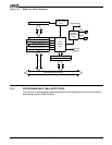

Timer Control Unit
9-4
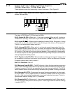
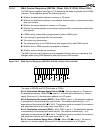
Bit 2: External Clock Bit (EXT)—When set to 1, an external clock is used. When set to
0, the internal clock is used. When the internal clock is used, the timer input pin is available
for use as a programmable I/O pin.
Bit 1: Alternate Compare Bit (ALT)—When set to 1, the timer counts to maxcount compare
A, then resets the count register to 0. Then the timer counts to maxcount compare B, resets
the count register to zero, and starts over with maxcount compare A.
If ALT is clear, the timer counts to maxcount compare A and then resets the count register
to zero and starts counting again against maxcount compare A. In this case, maxcount
compare B is not used.
Bit 0: Continuous Mode Bit (CONT)—When set to 1, CONT causes the associated timer
to run in the normal continuous mode.
When CONT is set to 0, EN is cleared after each timer count sequence and the timer clears
and then halts on reaching the maximum count. If CONT=0 and ALT=1, the timer counts
to the Maxcount Compare A register value and resets, then it counts to the B register value
and resets and halts.
Note: The TMRIN0, TMRIN1, TMROUT0, AND TMROUT1 pins are multiplexed with
programmable I/O pins. To enable the timer pin functionality, the PIO mode and PIO
direction settings for these pins must be set to 0 for normal operation. For more information,
see Chapter 13, “Programmable I/O Pins.”