


Interrupt Control Unit
8-33
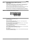
8.4.6 In-Service Register (INSERV, Offset 2Ch)
(Slave Mode)
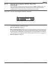
The format of the In-Service Register is shown in Figure 8-22. The bits in the In-Service
Register are set by the interrupt controller when the interrupt is taken. The in-service bits
are cleared by writing to the End-of-Interrupt (EOI) Register.
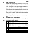
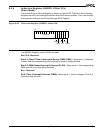
Figure 8-22 In-Service Register (INSERV, offset 2Ch)
The INSERV Register is set to 0000h on reset.
Bits 15–6: Reserved
Bits 5–4: Timer 2/Timer 1 Interrupt In-Service (TMR2–TMR1)—When set to 1, these bits
indicate that the corresponding timer interrupt is currently being serviced.
Bits 3–2: DMA Channel Interrupt In-Service (D1–D0)—When set to 1, the corresponding
DMA channel is currently being serviced.
Bit 1: Reserved
Bit 0: Timer 0 Interrupt In-Service (TMR0)—When set to 1, this bit indicates Timer 0 is
currently being serviced.
15
70
Reserved
D0
D1
TMR1
TMR2
Res
TMR0