


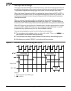


Interrupt Control Unit
8-12
8.2.3 Special Fully Nested Mode
Special fully nested mode is entered by setting the SFNM bit in the INT0 or INT1 control
registers. (See section 8.3.1 on page 8-14.) It enables complete nesting with external
82C59A masters or multiple interrupts from the same external interrupt pin when not in
Cascade mode. In this case, the ISRs must be re-entrant.
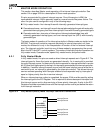
In fully nested mode, an interrupt request from an interrupt source is not recognized when
the in-service bit for that source is set. In this case, if more than one interrupt source is
connected to an external interrupt controller, all of the interrupts go through the same
Am186ER or Am188ER microcontroller interrupt request pin. As a result, if the external
interrupt controller receives a higher-priority interrupt, its interrupt is not recognized by the
microcontroller until the in-service bit is reset.
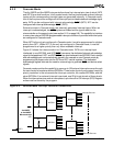
In special fully nested mode, the microcontroller’s interrupt controller allows the processor
to take interrupts from an external pin regardless of the state of the in-service bit for an
interrupt source. This allows multiple interrupts from a single pin. An in-service bit continues
to be set, however, to inhibit interrupts from other lower-priority Am186ER or Am188ER
microcontroller interrupt sources.
In special fully nested mode with Cascade mode, when a write is issued to the EOI Register
at the end of the interrupt service routine, software polling of the IS Register in the external
master 82C59A must determine if there is more than one IS bit set. If so, the IS bit in the
microcontroller remains active and the next ISR is entered.
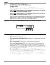
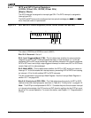
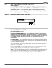
8.2.4 Operation in a Polled Environment
To allow reading of the Poll Register information without setting the indicated in-service bit,
the Am186ER and Am188ER microcontrollers provide a Poll Status Register (Figure 8-15)
in addition to the Poll Register. Poll Register information is duplicated in the Poll Status
Register, but the Poll Status Register can be read without setting the associated in-service
bit. These registers are located in two adjacent memory locations in the peripheral control
block.
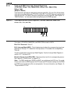
The interrupt controller can be used in polled mode if interrupts are not desired. When
polling, interrupts are disabled and software polls the interrupt controller as required. The
interrupt controller is polled by reading the Poll Status Register (Figure 8-15). Bit 15 in the
Poll Status Register indicates to the processor that an interrupt of high enough priority is
requesting service. Bits 4–0 indicate to the processor the interrupt type of the highest priority
source requesting service. After determining that an interrupt is pending, software reads
the Poll Register (rather than the Poll Status Register), which causes the in-service bit of
the highest priority source to be set.
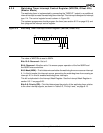
8.2.5 End-of-Interrupt Write to the EOI Register
A program must write to the EOI Register to reset the in-service (IS) bit when an interrupt
service routine is completed. There are two types of writes to the EOI Register—specific
EOI and non-specific EOI (see section 8.3.14 on page 8-28).
Non-specific EOI does not specify which IS bit is to be reset. Instead, the interrupt controller
automatically resets the IS bit of the highest priority source with an active service routine.
Specific EOI requires the program to send the interrupt type to the interrupt controller to indicate
the source IS bit that is to be reset. Specific reset is applicable when interrupt nesting is possible
or when the highest priority IS bit that was set does not belong to the service routine in progress.