


Interrupt Control Unit
8-8
8.1.5 Interrupt Acknowledge
Interrupts can be acknowledged in two different ways—the internal interrupt controller can
provide the interrupt type or an external interrupt controller can provide the interrupt type.
The processor requires the interrupt type as an index into the interrupt vector table.
When the internal interrupt controller is supplying the interrupt type and INT0 or INT1 is
programmed in Cascade mode, no interrupt acknowledge bus cycles are generated. The
only external indication that an interrupt is being serviced is the processor reading the
interrupt vector table.
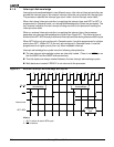
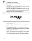
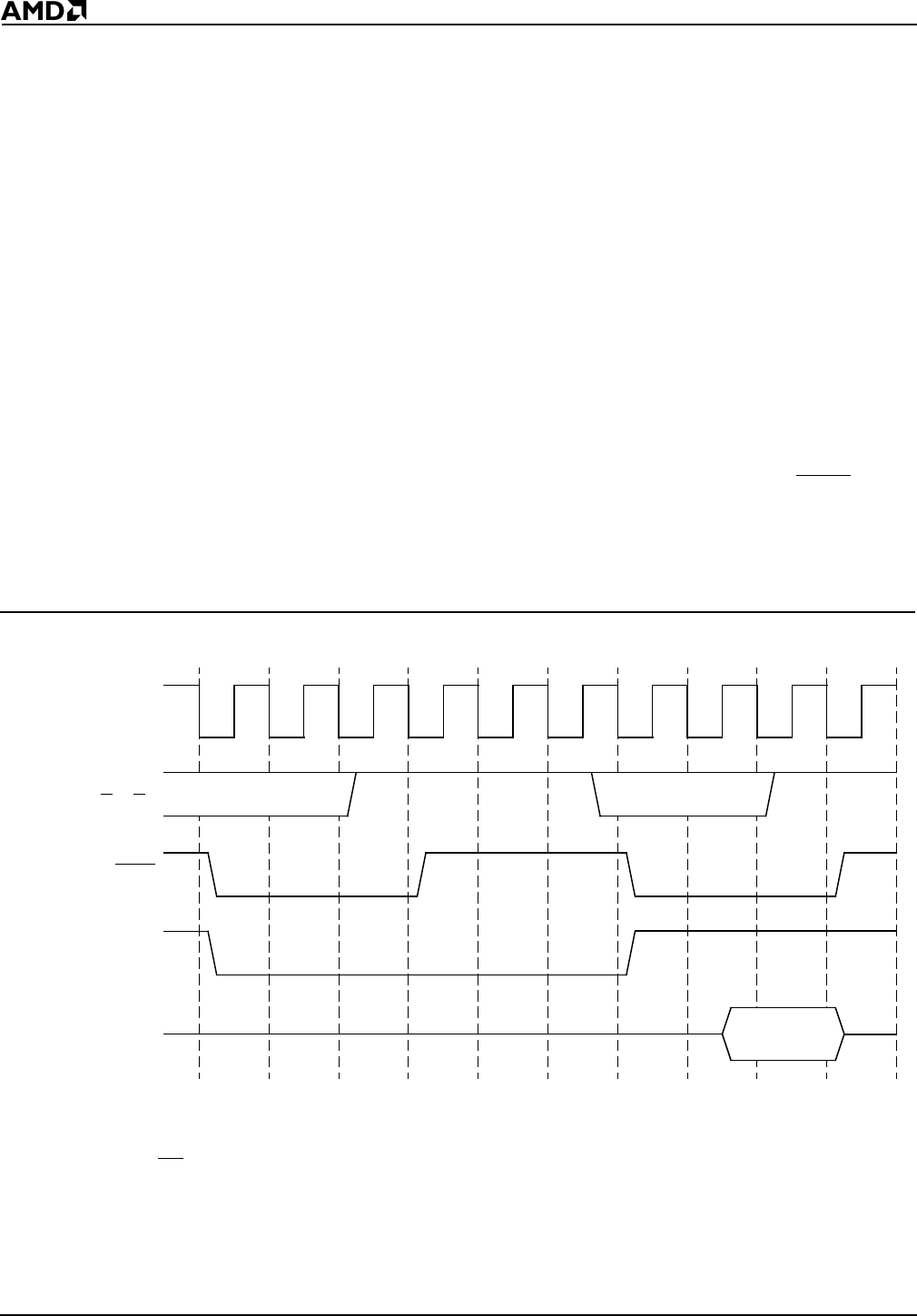
When an external interrupt controller is supplying the interrupt type, the processor
generates two interrupt acknowledge bus cycles (see Figure 8-1). The interrupt type is
written to the AD7–AD0 lines by the external interrupt controller during the second bus cycle.
When INT0 is the only pin configured in Cascade mode, it must be programmed to a higher
priority than INT1. When INT1 is the only pin configured in Cascade mode, it must be
programmed to a higher priority than any other maskable interrupt.
Interrupt acknowledge bus cycles have the following characteristics:
n The two interrupt acknowledge cycles are internally locked. (There is no LOCK pin on
the Am186ER and Am188ER microcontrollers.)
n Two idle states are always inserted between the two interrupt acknowledge cycles.
n Wait states are inserted if READY is not returned to the processor.
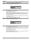
Figure 8-1 External Interrupt Acknowledge Bus Cycles
Notes:
1. ALE is active for each INTA cycle.
2. RD
is inactive.
T1 T2 T3 T4 T1 T2 T3 T4
S
0–S2
INTA
Internal lock
Ti Ti
Interrupt
Acknowledge
Interrupt
Acknowledge
AD7–AD0
Interrupt
Type