


Interrupt Control Unit
8-35
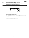
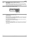
8.4.8 Interrupt Mask Register (IMASK, Offset 28h)
(Slave Mode)
The format of the Interrupt Mask Register is shown in Figure 8-24. The Interrupt Mask
Register is a read/write register. Programming a bit in the Interrupt Mask Register has the
effect of programming the MSK bit in the associated control register.
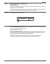
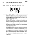
Figure 8-24 Interrupt Mask Register (IMASK, offset 28h)
The IMASK Register is set to 003Dh on reset.
Bits 15–6: Reserved
Bits 5–4: Timer 2/Timer 1 Interrupt Mask (TMR2–TMR1)—These bits indicate the state
of the mask bit of the Timer Interrupt Control Register and when set to a 1, indicate which
source has its interrupt requests masked.
Bits 3–2: DMA Channel Interrupt Mask (D1–D0)—These bits indicate the state of the
mask bits of the corresponding DMA control register.
Bit 1: Reserved
Bit 0: Timer 0 Interrupt Mask (TMR0)—This bit indicates the state of the mask bit of the
Timer Interrupt Control Register and when set to a 1, indicates Timer 0 has its interrupt
request masked.
15
70
Reserved
D0
D1
TMR1
TMR2
Res
TMR0