


System Overview
3-25
3.4.4 System Clocks
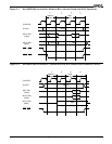
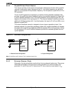
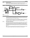
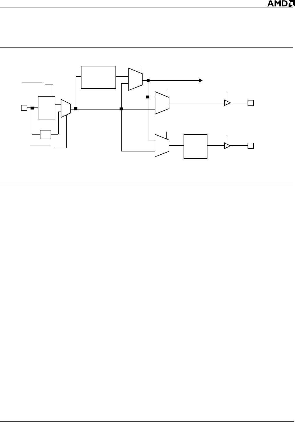
Figure 3-6 shows the organization of the clocks. The 80C186 microcontroller system clock
has been renamed CLKOUTA. CLKOUTB is provided as an additional output.
Figure 3-6 Clock Organization
CLKOUTA and CLKOUTB operate at either the CPU clock (power-save) frequency or the
fundamental clock (PLL or input divider) frequency. The output drivers for both clocks are
individually programmable for drive enable or disable.
The provision of two clock outputs lets the system designer configure one clock output to
run at the PLL frequency and the other to run at the CPU clock frequency. Individual drive
enable bits allow selective enabling of just one or both of these clock outputs.
3.4.5 Power-Save Operation
The power-save mode reduces power consumption and heat dissipation, which can reduce
power supply costs and size in all systems and extend battery life in portable systems. In
power-save mode, operation of the CPU and internal peripherals continues at a slower
clock frequency. When a hardware interrupt occurs, the CPU and internal peripheral clock
automatically returns to the fundamental clock frequency on the internal clock’s next rising
edge of t
3
.
Note: Power-save operation requires that clock-dependent devices be reprogrammed for
clock frequency changes. Software drivers must be aware of clock frequency.
Power-Save
Divisor
1
(/1 to /128)
CBF
1
Mux
CAF
1
Mux
PSEN
1
PLL
Mux
CLKOUTA
CLKOUTB
X1, X2
CPU Clock
Time
Delay
6
± 2.5ns
÷2
Input Clock
CLKSEL2
CLKSEL
1
CAD
1
CBD
1
Fundamental
Clock
1x or 4x
Mux
Notes:
1. Set via PDCON Register