


Programming
2-2
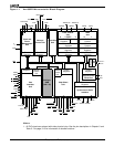
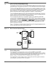
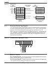
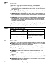
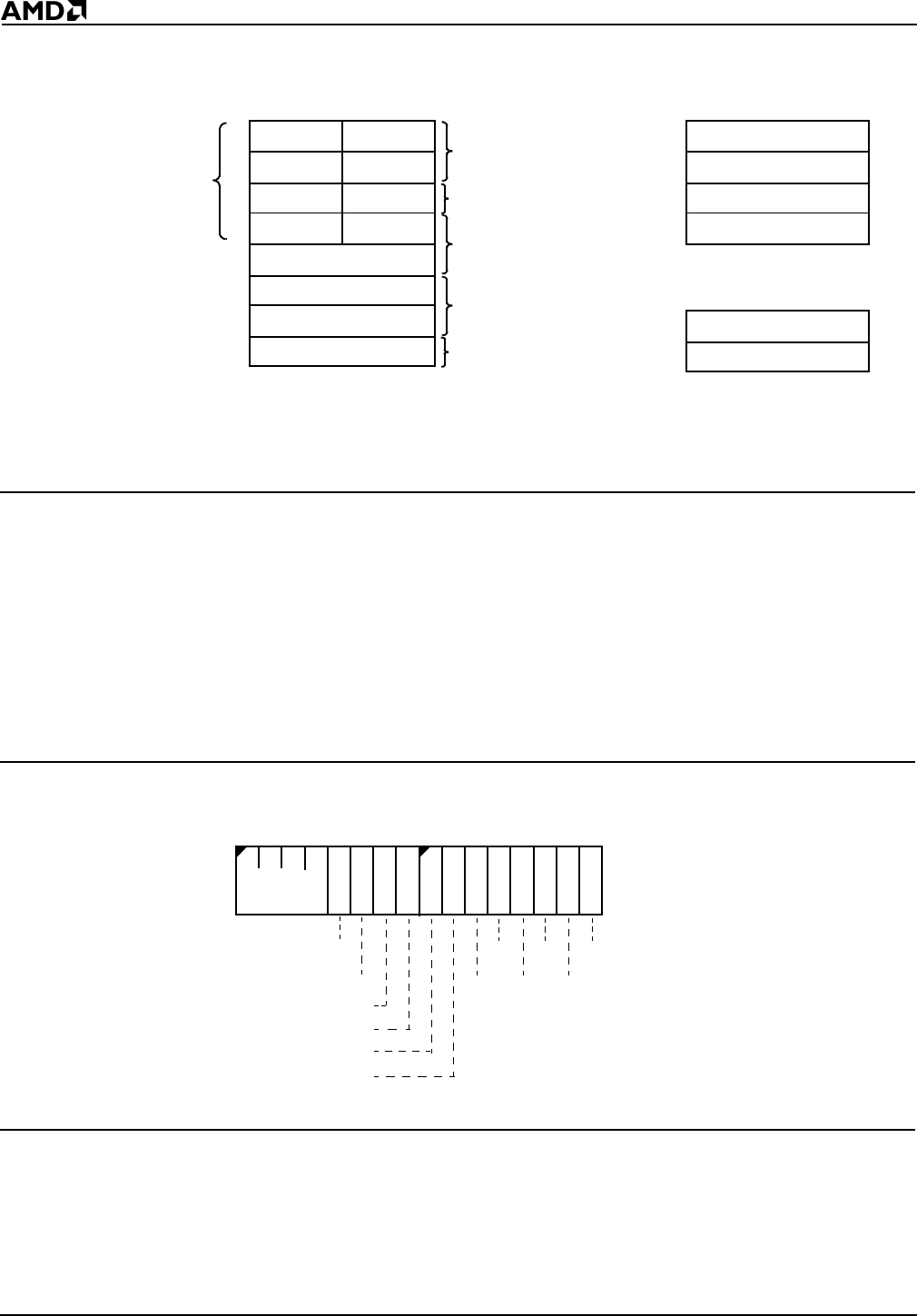
Figure 2-1 Register Set
2.1.1 Processor Status Flags Register
The 16-bit processor Status Flags Register (Figure 2-2) records specific characteristics of
the result of logical and arithmetic instructions (bits 0, 2, 4, 6, 7, and 11) and controls the
operation of the microcontroller within a given operating mode (bits 8, 9, and 10).
After an instruction is executed, the value of the flags may be set (to 1), cleared/reset (set
to 0), unchanged, or undefined. The term
undefined
means that the flag value prior to the
execution of the instruction is not preserved, and the value of the flag after the instruction is
executed cannot be predicted.
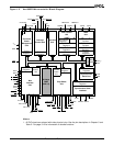
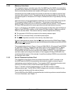
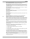
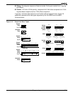
Figure 2-2 Processor Status Flags Register (FLAGS)
Bits 15–12—Reserved
Bit 11: Overflow Flag (OF)—Set if the signed result cannot be expressed within the number
of bits in the destination operand; cleared otherwise.
Bit 10: Direction Flag (DF)—Causes string instructions to auto-decrement the appropriate
index registers when set. Clearing DF causes auto-increment.
AH
Byte
Addressable
(8-Bit
Register
Names
Shown)
Loop/Shift/Repeat/Count
Base Registers
Code Segment
Data Segment
Stack Segment
Extra Segment
Processor Status Flags
Instruction Pointer
General
Registers
Status and Control
Registers
Segment Registers
15 0
15 0
7 0 7 0
15 0
CS
FLAGS
IP
16-Bit
Register Name
Special Register
Functions
DS
SS
ES
AX
DX
CX
BX
BP
SI
DI
SP
DH
CH
BH
AL
DL
CL
BL
Index Registers
Stack Pointer
Multiply/Divide
I/O Instructions
Base Pointer
Source Index
Destination Index
16-Bit
Register Name
15
70
IF
TF
SF
ZF
Res
CF
PF
Reserved
Res
AF
Res
OF
DF