


Interrupt Control Unit
8-23
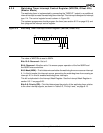
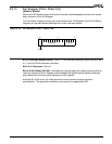
8.3.9 In-Service Register (INSERV, Offset 2Ch)
(Master Mode)
The bits in the In Service (INSERV) Register are set by the interrupt controller when the
interrupt is taken. Each bit in the register is cleared by writing the corresponding interrupt
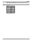
type to the End-of-Interrupt (EOI) Register. See Table 8-1, “Am186ER and Am188ER
Microcontroller Interrupt Types,” on page 8-3.
When an in-service bit is set, the microcontroller will not generate an interrupt request for
the associated source, preventing an interrupt from interrupting itself if interrupts are
enabled in the ISR. Special fully nested mode allows the INT1–INT0 requests to circumvent
this restriction for the INT0 and INT1 sources.
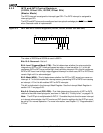
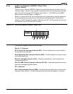
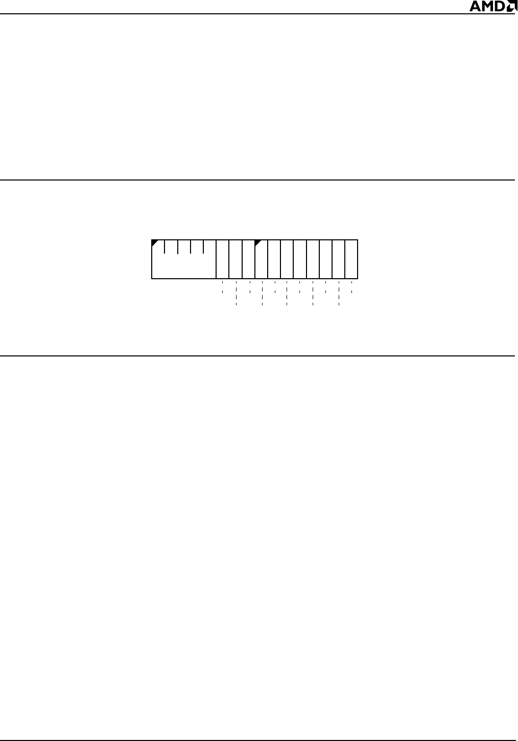
Figure 8-12 In-Service Register (INSERV, offset 2Ch)
The INSERV Register is set to 0000h on reset.
Bits 15–11: Reserved
Bit 10: Serial Port Interrupt In-Service (SPI)—This bit indicates the in-service state of
the asynchronous serial port.
Bit 9: Watchdog Timer Interrupt In-Service (WD)—This bit indicates the in-service state
of the Watchdog Timer.
Bits 8–4: Interrupt In-Service (I4–I0)—These bits indicate the in-service state of the
corresponding INT pin.
Bits 3–2: DMA Channel Interrupt In-Service (D1–D0)—These bits indicate the in-service
state of the corresponding DMA channel.
Bit 1: Reserved
Bit 0: Timer Interrupt In-Service (TMR)—This bit indicates the state of the in-service timer
interrupts. When set to a 1, this bit indicates that a timer interrupt request is in-service.
15
70
Reserved
Res
TMRD0
D1
I0
I1
I2
I3
I4
WD
SPI