


System Overview
3-23
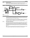
3.4 CLOCK AND POWER MANAGEMENT UNIT
The clock and power management unit of the Am186ER and Am188ER microcontrollers
includes a phase-locked loop (PLL) and a second programmable system clock output
(CLKOUTB).
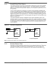
3.4.1 Phase-Locked Loop (PLL)
In a traditional 80C186/188 design, the crystal frequency is twice that of the desired internal
clock. Because of the internal PLL on the Am186ER and Am188ER microcontrollers, the
internal clock generated by the microcontroller (CLKOUTA) can operate at up to four times
the frequency of the crystal. The Am186ER and Am188ER microcontrollers operate in the
following modes:
n Divide by Two—The frequency of the system clock is half the frequency of the crystal.
PLL is disabled.
n Times One—The frequency of the system clock is the same as the external crystal. PLL
is enabled.
n Times Four—The frequency of the system clock is four times the frequency of the crystal.
PLL is enabled.
The default Times Four mode must be used for processor frequencies above 20 MHz.
Times One mode must be used for operation between 16 and 20 MHz. The clocking mode
is selected using CLKSEL
1 and CLKSEL2 on reset. Table 3-5 provides the maximum and
minimum frequencies for X1, X2, and CLKOUTA according to clocking mode.
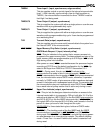
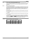
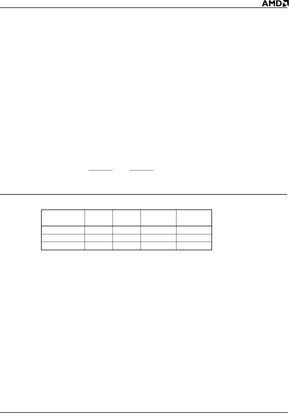
Table 3-5 Maximum and Minimum Clock Frequencies
Mode
X1/X2
Max
X1/X2
Min
CLKOUTA
Max
CLKOUTA
Min
Divide by Two 20 MHz —10 MHz —
Times One 20 MHz 16 MHz 20 MHz 16 MHz
Times Four 10 MHz 5 MHz 40 MHz 20 MHz