


Programmable I/O Pins
13-1
CHAPTER
13
PROGRAMMABLE I/O PINS
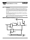
13.1 OVERVIEW
Thirty-two pins on the Am186ER and Am188ER microcontrollers are available as user-
programmable I/O signals (PIOs). Each of these pins can be used as a PIO if the normal
function of the pin is not needed. If a pin is enabled to function as a PIO signal, the normal
function is disabled and does not affect the pin. A PIO signal can be configured to operate
as an input or output with or without internal pullup or pulldown resistors, or as an open-
drain output.
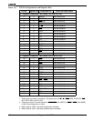
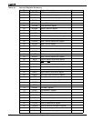
After power-on reset, the PIO pins default to various configurations. The column titled
Power-On Reset Status
in Table 13-1 lists the defaults for the PIOs. The system initialization
code must reconfigure PIOs as required.
The A19–A17 address pins default to normal operation on power-on reset, allowing the
processor to correctly begin fetching instructions at the boot address FFFF0h. The DT/R
,
DEN
, and SRDY pins also default to normal operation on power-on reset.
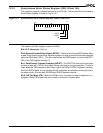
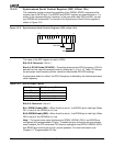
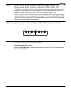
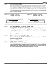
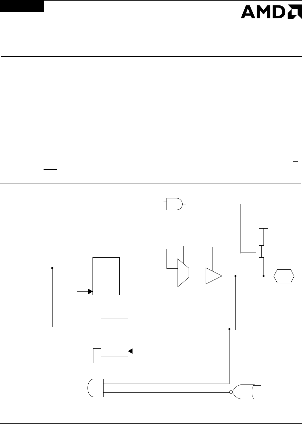
Figure 13-1 Programmable I/O Pin Operation
VCC
Pin
D
40 MHz
(CLK)
OE
RD
PDATA
Normal
Function
0
1
PIO
Mode
PIO
Direction
Q
Int.
Bus
Q
D
Mode
Dir.
WR
PDATA
PIOTRI
PIOPULL
Data In
PIODRV
Normal
Data In