


Timer Control Unit
9-3
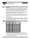
9.2.2 Timer 0 and Timer 1 Mode and Control Registers
(T0CON, Offset 56h, T1CON, Offset 5Eh)
These registers control the functionality of timer 0 and timer 1. See Figure 9-1.
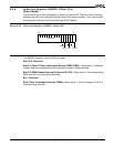
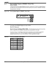
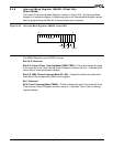
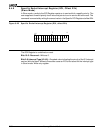
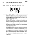
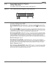
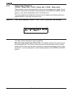
Figure 9-1 Timer 0 and Timer 1 Mode and Control Registers (T0CON, T1CON,
offsets 56h and 5Eh)
The value of T0CON and T1CON at reset is 0000h.
Bit 15: Enable Bit (EN)—When set to 1, the timer is enabled. When set to 0, the timer is
inhibited from counting. This bit can only be written with the INH
bit set at the same time.
Bit 14: Inhibit Bit (INH
)—Allows selective updating of enable (EN) bit. When set to 1 during
a write, EN can also be modified. When set to 0 during a write, writes to EN are ignored.
This bit is not stored and is always read as 0.
Bit 13: Interrupt Bit (INT)—When set to 1, an interrupt request is generated when the
count register equals a maximum count. If the timer is configured in dual maxcount mode,
an interrupt is generated each time the count reaches maxcount A or maxcount B. When
INT is set to 0, the timer will not issue interrupt requests. If the enable bit is cleared after
an interrupt request has been generated but before the pending interrupt is serviced, the
interrupt request will still be present.
Bit 12: Register in Use Bit (RIU)—When the Maxcount Compare A register is being used
for comparison to the timer count value, this bit is set to 0. When the Maxcount Compare
B register is being used, this bit is set to 1.
Bits 11–6: Reserved—Set to 0.
Bit 5: Maximum Count Bit (MC)—The MC bit is set to 1 when the timer reaches a maximum
count. In dual maxcount mode, the bit is set each time either the Maxcount Compare A or
B register is reached. This bit is set regardless of the timer interrupt-enable bit. The MC bit
can be used to monitor timer status through software polling instead of through interrupts.
Bit 4: Retrigger Bit (RTG)—Determines the control function provided by the timer input
pin. When set to 1, a 0 to 1 edge transition on TMRIN0 or TMRIN1 resets the count. When
set to 0, a High input enables counting and a Low input holds the timer value. This bit is
ignored when external clocking (EXT=1) is selected.
Bit 3: Prescaler Bit (P)—When set to 1, the timer is prescaled by timer 2. When set to 0,
the timer counts up every fourth CLKOUT period. This bit is ignored when external clocking
is enabled (EXT=1).
15
70
EN
INT
INH RIU
0
P
EXT
MC
RTG
ALT
CONT
00000