


Interrupt Control Unit
8-17
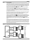
8.3.3 INT4 Control Register (I4CON, Offset 40h)
(Master Mode)
The Am186ER and Am188ER microcontrollers provide INT4, an additional external
interrupt pin. This input behaves like INT3–INT0 on the 80C186/188 microcontroller with
the exception that INT4 is only intended for use as a nested-mode interrupt source.
This interrupt is assigned to interrupt type 10h. The Interrupt 4 Control Register (see Figure
8-6) controls the operation of the INT4 signal.
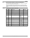
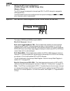
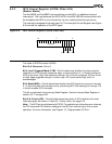
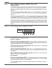
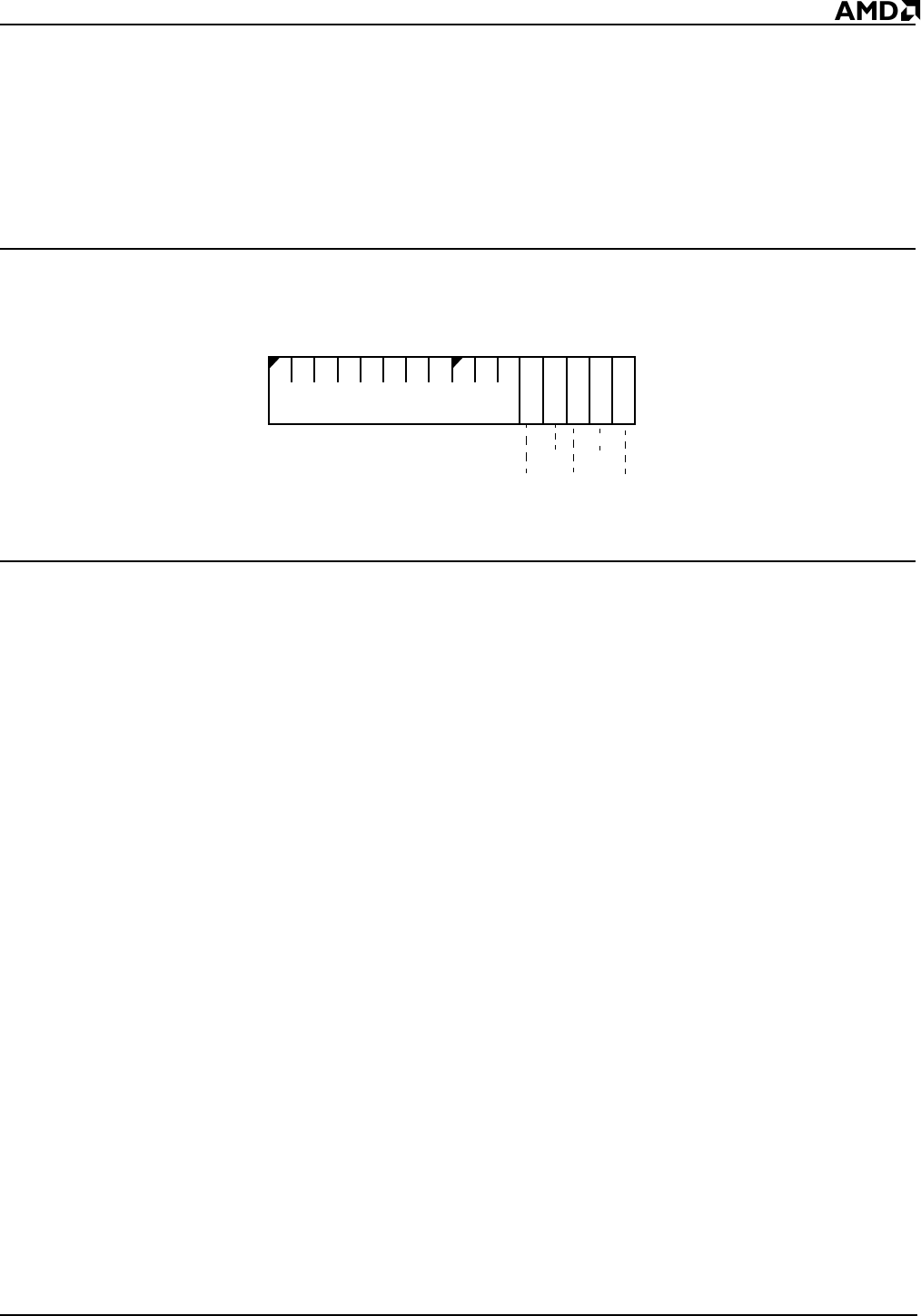
Figure 8-6 INT4 Control Register (I4CON, offset 40h)
The value of I4CON at reset is 000Fh.
Bits 15–5: Reserved—Set to 0.
Bit 4: Level-Triggered Mode (LTM)—This bit determines whether the microcontroller
interprets an INT4 interrupt request as edge- or level-sensitive. A 1 in this bit configures
INT4 as an active High, level-sensitive interrupt. A 0 in this bit configures INT4 as a Low-
to-High, edge-triggered interrupt. In either case, INT4 must remain High until it is
acknowledged.
Bit 3: Mask (MSK)—This bit determines whether the INT4 signal can cause an interrupt.
A 1 in this bit masks this interrupt source, preventing INT4 from causing an interrupt. A 0
in this bit enables INT4 interrupts.
This bit is duplicated in the Interrupt Mask Register. See the Interrupt Mask Register in
section 8.3.11 on page 8-25.
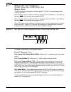
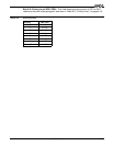
Bits 2–0: Priority (PR)—This field determines the priority of INT4 relative to the other
interrupt signals, as shown in Table 8-3, “Priority Level,” on page 8-15.
Note: The INT4 pin is multiplexed with PIO 30. To enable the pin to function as an interrupt,
the PIO mode and PIO direction settings for the INT4 pin must be set to 0 for normal
operation. For more information, see Chapter 13, “Programmable I/O Pins.”
15
70
MSK
LTM
Reserved
PR2
PR1
PR0