


Interrupt Control Unit
8-2
The processor calculates the index to the interrupt vector table by shifting the interrupt type
left 2 bits (multiplying by 4).
8.1.1.3 Maskable and Nonmaskable Interrupts
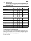
Interrupt types 08h through 1Fh are maskable. Of these, only 08h through 14h are actually
in use (see Table 8-1). The maskable interrupts are enabled and disabled by the interrupt
enable flag (IF) in the processor status flags, but the INT command can execute any interrupt
regardless of the setting of IF.
Interrupt types 00h through 07h and all software interrupts (the INT instruction) are
nonmaskable. The nonmaskable interrupts are not affected by the setting of the IF flag.
The Am186ER and Am188ER microcontrollers provide two methods for masking and
unmasking the maskable interrupt sources. Each interrupt source has an interrupt control
register that contains a mask bit specific to that interrupt. In addition, the Interrupt Mask
Register is provided as a single source to access all of the mask bits.
If the Interrupt Mask Register is written while interrupts are enabled, it is possible that an
interrupt could occur while the register is in an undefined state. This can cause interrupts
to be accepted even though they were masked both before and after the write to the Interrupt
Mask Register. Therefore, the Interrupt Mask Register should only be written when
interrupts are disabled. Mask bits in the individual interrupt control registers can be written
while interrupts are enabled, and there will be no erroneous interrupt operation.
8.1.1.4 Interrupt Enable Flag (IF)
The interrupt enable flag (IF) is part of the processor status flags (see section 2.1.1 on page
2-2). If IF is set to 1, maskable interrupts are enabled and can cause processor interrupts.
(Individual maskable interrupts can still be disabled by means of the mask bit in each control
register.)
If IF is set to 0, all maskable interrupts are disabled.
The IF flag does not affect the NMI or software exception interrupts (interrupt types 00h to
07h), and it does not affect the execution of any interrupt through the INT instruction.
8.1.1.5 Interrupt Mask Bit
Each of the interrupt control registers for the maskable interrupts contains a mask bit (MSK).
If MSK is set to 1 for a particular interrupt, that interrupt is disabled regardless of the IF
setting.
8.1.1.6 Interrupt Priority
The column titled
Overall Priority
in Table 8-1 shows the fundamental priority breakdown
for the interrupts at power-on reset. The nonmaskable interrupts 00h through 07h are always
prioritized ahead of the maskable interrupts.
The maskable interrupts can be reprioritized by reconfiguring the PR2–PR0 bits in the
interrupt control registers. The PR2–PR0 bits in all the maskable interrupts are set to priority
level 7 at power-on reset.
8.1.1.7 Software Interrupts
Software interrupts can be initiated by the INT instruction. Any of the 256 possible interrupts
can be initiated by the INT instruction. INT 21h causes an interrupt to the vector located at
00084h in the interrupt vector table. INT FFh causes an interrupt to the vector located at
003FCh in the interrupt vector table. Software interrupts are not maskable and are not
affected by the setting of the IF flag.