


Features and Performance
1-4
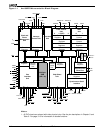
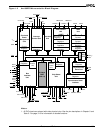
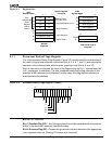
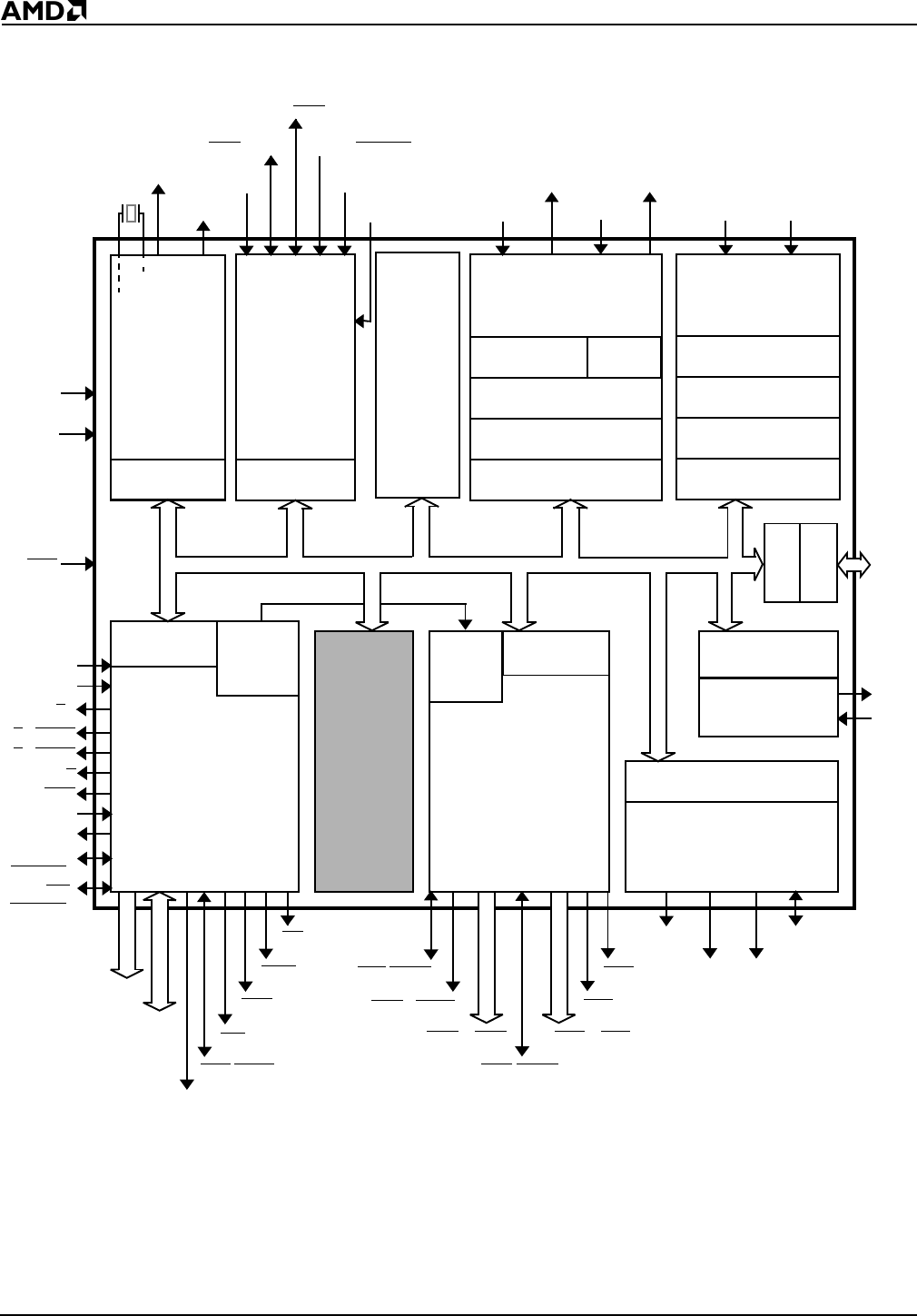
Figure 1-1 Am186ER Microcontroller Block Diagram
Notes:
1. All PIO signals are shared with other physical pins. See the pin descriptions in Chapter 3 and
Table 3-1 on page 3-10 for information on shared functions.
Registers
Control
S2
Interrupt
Control Unit
Timer Control
Unit
DMA
Unit
Bus
Interface
Unit
Execution
Unit
Chip-Select
Unit
Clock and
Power
Management
Unit
Control
Registers
16-Bit Count
Registers
Max Count A
Registers
16-Bit Count
Registers
20-Bit Destination
Pointers
20-Bit Source
Pointers
Control
Registers
Control
Registers
Control
Registers
01 (WDT)2 0 1
Max Count B
Registers
Refresh
Control
Unit
Control
Registers
Control
Registers
Control
Registers
CLKOUTB
CLKOUTA
INT4
INT3/INTA
1/IRQ
INT2/INTA
0
INT1/SELECT
INT0
TMROUT0 TMROUT1
DRQ0 DRQ1
V
CC
GND
TMRIN0 TMRIN1
ARDY
SRDY
DT/R
DEN
HOLD
HLDA
Asynchronous
Serial Port
Synchronous Serial
Interface
TXD
RXD
SCLK
SDATA
SDEN0 SDEN1
NMI
A19–A0
AD15–AD0
ALE
BHE
/ADEN
WR
WLB
WHB
RD
RES
LCS/ONCE0
MCS
2–MCS0
PCS
6/A2
PCS
3–PCS0
PCS
5/A1
UCS/ONCE1
X2
X1
Control
Registers
PSRAM
Control
Unit
MCS3/RFSH
PIO
Unit
PIO31–
PIO0
1
S6/
UZI
/
CLKSEL
2
CLKSEL
1
32 Kbyte
RAM
(16K x 16)
S1/IMDIS
S0/SREN