


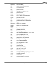

Programming
2-3
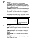
Bit 9: Interrupt-Enable Flag (IF)—When set, enables maskable interrupts to cause the
CPU to transfer control to a location specified by an interrupt vector.
Bit 8: Trace Flag (TF)—When set, a trace interrupt occurs after instructions execute. TF
is cleared by the trace interrupt after the processor status flags are pushed onto the stack.
The trace service routine can continue tracing by popping the flags back with an interrupt
return (IRET) instruction.
Bit 7: Sign Flag (SF)—Set equal to high-order bit of result (0 if 0 or positive, 1 if negative).
Bit 6: Zero Flag (ZF)—Set if result is 0; cleared otherwise.
Bit 5: Reserved
Bit 4: Auxiliary Carry (AF)—Set on carry from or borrow to the low-order 4 bits of the AL
general-purpose register; cleared otherwise.
Bit 3: Reserved
Bit 2: Parity Flag (PF)—Set if low-order 8 bits of result contain an even number of 1 bits;
cleared otherwise.
Bit 1: Reserved
Bit 0: Carry Flag (CF)—Set on high-order bit carry or borrow; cleared otherwise.
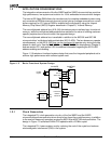
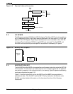
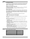
2.2 MEMORY ORGANIZATION AND ADDRESS GENERATION
Memory is organized in sets of segments. Each segment is a linear contiguous sequence
of 64K (2
16
) 8-bit bytes. Memory is addressed using a two-component address that consists
of a 16-bit segment value and a 16-bit offset. The offset is the number of bytes from the
beginning of the segment (the segment address) to the data or instruction that is being
accessed.
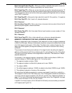
The processor forms the physical address of the target location by taking the segment
address, shifting it to the left 4 bits (multiplying by 16), and adding this to the 16-bit offset.
The result is the 20-bit address of the target data or instruction. This allows for a 1-Mbyte
physical address size.
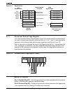
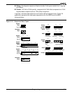
For example, if the segment register is loaded with 12A4h and the offset is 0022h, the
resultant address is 12A62h (see Figure 2-3). To find the result:
1. The segment register contains 12A4h.
2. The segment register is shifted left 4 places and is now 12A40h.
3. The offset is 0022h.
4. The shifted segment address (12A40h) is added to the offset (00022h) to get 12A62h.
5. This address is placed on the pins of the controller.
All instructions that address operands in memory must specify (implicitly or explicitly) a
16-bit segment value and a 16-bit offset value. The 16-bit segment values are contained in
one of four internal segment registers (CS, DS, ES, and SS). See “Addressing Modes” on
page 2-10 for more information on calculating the offset value. See “Segments” on page
2-8 for more information on CS, DS, ES, and SS.
In addition to memory space, all Am186 and Am188 family microcontrollers provide 64K
of I/O space (see Figure 2-4).