


Interrupt Control Unit
8-13
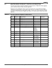
8.3 MASTER MODE INTERRUPT CONTROLLER REGISTERS
The interrupt controller registers for Master mode are shown in Table 8-2. All the registers
can be read and written unless otherwise specified.
Registers can be redefined in Slave mode. See section 8.4 on page 8-29 for detailed
information regarding Slave mode register usage. On reset, the microcontroller is in Master
mode. Bit 14 of the Relocation Register (see Figure 4-2) must be set to initiate Slave mode
operation.
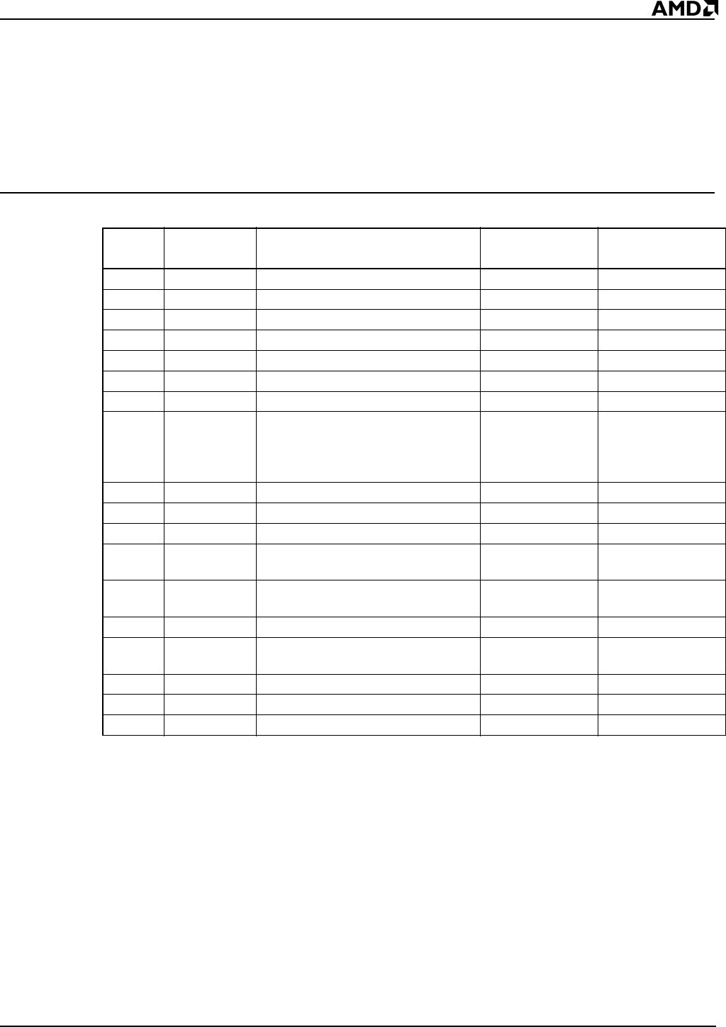
Table 8-2 Interrupt Controller Registers in Master Mode
Offset
Register
Mnemonic Register Name
Associated
Pins Comments
3Ah I1CON INT1 Control INT1
38h I0CON INT0 Control INT0
3Eh I3CON INT3 Control INT3
3Ch I2CON INT2 Control INT2
40h I4CON INT4 Control INT4
36h DMA1CON DMA1 Interrupt Control DRQ1
34h DMA0CON DMA0 Interrupt Control DRQ0
32h TCUCON Timer Interrupt Control TMRIN1
TMRIN0
TMROUT1
TMROUT0
42h WDCON Watchdog Timer Interrupt Control
44h SPICON Serial Port Interrupt Control TXD, RXD
30h INTSTS Interrupt Status
2Eh REQST Interrupt Request INT4–INT0
DRQ1–DRQ0
Read-only register
2Ch INSERV In-Service INT4–INT0
DRQ1–DRQ0
2Ah PRIMSK Priority Mask
28h IMASK Interrupt Mask INT4–INT0
DRQ1–DRQ0
26h POLLST Poll Status Read-only register
24h POLL Poll Read-only register
22h EOI End of Interrupt Write-only register