


System Overview
3-24
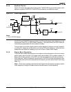
3.4.2 Crystal-Driven Clock Source
The internal oscillator circuit of the microcontroller is designed to function with a parallel
resonant fundamental crystal. Because of the PLL, the crystal frequency can be twice,
equal to, or one quarter of the processor frequency. Do not replace a crystal with an LC or
RC equivalent.
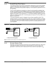
The X1 and X2 signals are connected to an internal inverting amplifier (oscillator) that
provides, along with the external feedback loading, the necessary phase shift (Figure 3-5).
In such a positive feedback circuit, the inverting amplifier has an output signal (X2) 180
degrees out of phase of the input signal (X1). The external feedback network provides an
additional 180-degree phase shift. In an ideal system, the input to X1 will have 360 or zero
degrees of phase shift.
The external feedback network is designed to be as close as possible to ideal. If the
feedback network is not providing necessary phase shift, negative feedback will dampen
the output of the amplifier and negatively affect the operation of the clock generator. Values
for the loading on X1 and X2 must be chosen to provide the necessary phase shift and
crystal operation.
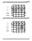
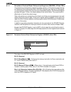
Figure 3-5 Oscillator Configurations
3.4.3 External Source Clock
Alternately, the internal oscillator can be driven from an external clock source. This source
should be connected to the input of the inverting amplifier (X1) with the output (X2)
grounded. X1 and X2 are not 5-V tolerant and X1 has a maximum input equal to V
CC
.
Crystal
X1
b. Crystal Configuration
C
1
C
2
X2
To PLL
Oscillator
a. External Clock Configuration
Microcontroller
Am188ER/
X1
X2
To PLL
Oscillator
Am186ER
Microcontroller
Am188ER/
Am186ER
Note: X1 and X2 are not 5-V tolerant. The X1 maximum input is V
CC
.