


System Overview
3-17
WR Write Strobe (output, synchronous)
WR
—This pin indicates to the system that the data on the bus is to be
written to a memory or I/O device. WR
is three-stated during a bus hold
or reset condition.
X1 Crystal Input (input)
This pin and the X2 pin provide connections for a fundamental mode
crystal used by the internal oscillator circuit. If providing an external
clock source, connect the source to X1 and ground X2. Unlike the rest
of the pins on the Am186ER and Am188ER microcontrollers, X1 is not
5-V tolerant and has a maximum input equal to V
CC
.
X2 Crystal Output (output)
This pin and the X1 pin provide connections for a fundamental mode
crystal used by the internal oscillator circuit. If providing an external
clock source, connect the source to X1 and ground X2. Unlike the rest
of the pins on the Am186ER and Am188ER microcontrollers, X2 is not
5-V tolerant and has a maximum input equal to V
CC
.
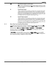
3.1.1 Pins That Are Used by Emulators
The following pins are used by emulators: A19–A0, AO15–AO8, AD7–AD0, ALE, BHE/
ADEN
(on the Am186ER microcontroller), CLKOUTA, RFSH2/ADEN (on the Am188ER
microcontroller), RD
, S2, S1/IMDIS, S0/SREN, S6/CLKSEL1, and UZI/CLKSEL2.
Emulators require that S6/CLKSEL
1 and UZI/CLKSEL2 be configured in their normal
functionality, that is, as S6 and UZI
.
If BHE
/ADEN (on the Am186ER microcontroller) or RFSH2/ADEN (on the Am188ER
microcontroller) is held Low during the rising edge of RES
, S6 and UZI are configured in
their normal functionality, instead of as PIOs, at reset.