


Synchronous Serial Interface
12-1
CHAPTER
12
SYNCHRONOUS SERIAL INTERFACE
12.1 OVERVIEW
The synchronous serial interface enables the Am186ER and Am188ER microcontrollers
to communicate with application-specific integrated circuits (ASICs) that require
programmability but are short on pins. The four-pin interface permits half-duplex,
bidirectional data transfer at speeds of up to 20 Mbit/s with a 40-MHz CPU clock.
Unlike the asynchronous serial port, the SSI operates in a master/slave configuration. The
Am186ER and Am188ER microcontrollers operate as the master port.
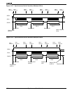
The SSI interface provides four pins for communicating with system components: two
enables (SDEN0 and SDEN1), a clock (SCLK), and a data pin (SDATA). Five registers
(see Table 12-1) are used to control and monitor the interface.
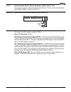
n The Synchronous Serial Status register (SSS) reports the current port status.
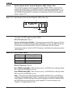
n The Synchronous Serial Control register (SSC) sets the port clock rate and controls the
enable signals.
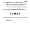
n There are two data transmit registers—the Synchronous Serial Transmit 0 register
(SSD0) and the Synchronous Serial Transmit 1 register (SSD1)—but data is transmitted
and received over a single pin (SDATA).
n The Synchronous Serial Receive Register (SSR) holds data received over the SSI.
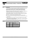
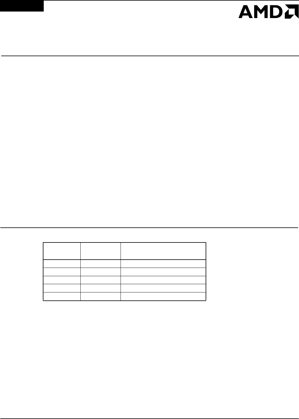
Table 12-1 Synchronous Serial Interface Register Summary
Offset from
PCB
Register
Mnemonic Register Name
10h SSS Synchronous Serial Status
12h SSC Synchronous Serial Control
14h SSD1 Synchronous Serial Transmit 1
16h SSD0 Synchronous Serial Transmit 0
18h SSR Synchronous Serial Receive