


4535 612 34161 HD3 Service Manual Page 65
CSIP Level 1 Theory of Operation: Functional Description
• 25 MHz system clock
• COM port
• LCD Interface
• PCI Interface
• Non-interlace to VGA conversion
• Non-interlace to interlace conversion
• Doppler sound
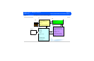
E-box Backplane
The Backplane (Motherboard) is the physical and functional “backbone” of the ultrasound
engine. It is connected to the power supply, from which it receives DC operating voltages to dis-
tribute to the system components via a power bus and power cabling. The Backplane also pro-
vides control and signal interconnection between the system components via buses and signal
cabling. The FE, BF, DSC, and PCC boards are all plugged into connectors on the Backplane.
Input/Output
Panel
The I/O Panel at the rear of the system includes a circuit board that accomplishes the intercon-
nection between system components and peripheral devices (see Figure 11-5 for connection
descriptions).
User Interface
The user interface comprises the controls, indicators, and output devices of the system.
The control panel (in conjunction with the monitor displays) is the primary operating interface
with the ultrasound system. The footswitch, with freeze and display change functions, is an
extension of the control panel.
The control panel consists of TGC slide pot controls, trackball, additional system control knobs
and buttons, and a QWERTY keyboard. An internal interface PCB reads all of the control inputs,
determines the function that has been selected, and transmits that information to the PCC for
processing.