


4535 612 34161 HD3 Service Manual Page 59
CSIP Level 1 Theory of Operation: Functional Description
Functional
Description
The HD3 system produces ultrasound images using transducers, digital beamforming, and Dop-
pler processing. The central processing unit of the system is the PCC Board. The ultrasound
components comprise digital beamformer technology that combines with the operating system
to support the system functions.
The HD3 system stores the ultrasound images and patient data on the hard drive and can copy
that data to the removable media, such as magneto-optical drive (MOD) disks, CD-R and
CD-R/W disks, and USB flash memory sticks for off-system review. The system can send the
images to a black-and-white printer, color printer, or to a VCR. It also generates reports that can
be printed.
After operating power is applied, the major functional elements combine to produce ultrasound
images. The user interface allows system control and viewing of the results.
The overall system functional flow is power development and distribution, analog signal process-
ing, beamforming, continuous-wave and color Doppler processing, scan conversion, digital signal
processing, and video and audio presentation.
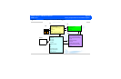
The HD3 system ultrasound engine physically and functionally comprises five primary circuit
boards, the TCA (page 63), the FE (page 63), the BF (page 63), the DSC (page 63), and the PCC
(page 64). Most of the ultrasound signal processing, image processing, analysis, and display func-
tions are performed by software using the native processing power of the embedded computer
of the PCC Board.
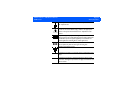
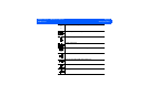
Figure 4-1 is a simplified block diagram of the HD3 system, showing the relationship between the
primary circuit boards and indicating the major functional tasks performed by each.