


4535 612 34161 HD3 Service Manual Page 38
CSIP Level 1 General Information: Physical Description
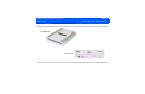
Transducer Connector Assembly
The Transducer Connector Assembly (TCA) has the transducer connectors (contained in metal
shielding) that interconnect to the E-box Front End board.
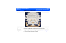
E-box
The E-box is a card cage that houses the ultrasound signal generation and echo acquisition cir-
cuits. The following ultrasound system electronic circuits are contained in the E-box:
• E-box Motherboard (backplane)
• Front End (FE) Assembly
• Beamformer (BF) Board
• Beamformer-to-Front End Connector (BFC) (physically and electronically connects BF and FE
boards)
• Digital Scan Converter (DSC) Board
• PCC Board (embedded computer)
System Power
Components
The system electronic power components are the Isolation Transformer, Power Supply, and the
Power I/O Assembly.
See Section 14, “Parts” for illustrations and locations of these system components.
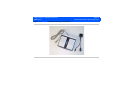
Software and
Data Storage
Components
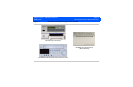
The software and data storage components (Figure 1-3) are physically comprised of the hard disk
drive (HDD), CD-RW drive, and when installed, the optional magneto-optical disk (MOD) drive.