


4535 612 34161 HD3 Service Manual Page 178
CSIP Level 2 Disassembly: Disassembly (Removal) Procedures
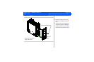
E-box Bay (E-box Assembly, Transducer Connector
Assembly, E-box Boards, Power Supply and Cooling Fans)
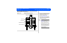
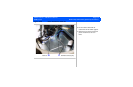
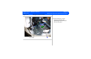
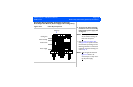
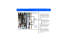
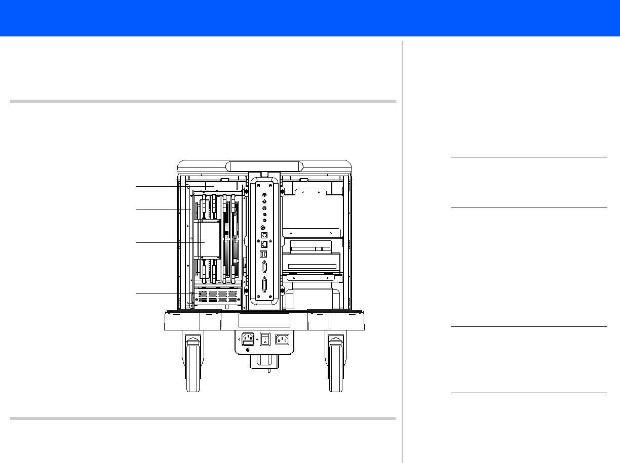
Figure 10-24 E-box Bay Components
E-box bay
E-box assembly
Power supply
1
E-box boards
Cooling fans
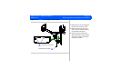
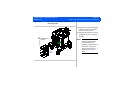
➤ To remove the E-box assembly,
transducer connector assembly,
E-box boards, power supply and
cooling fans
NOTE You can perform most E-box
service without removing the
E-box from the system.
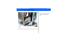
1. Refer to Figure 10-3, Figure 10-4,
and Figure 10-5 for system enclosure
removal before proceeding with the
following procedures. To remove the
transducer connector assembly, pro-
ceed to step 14.
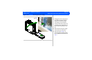
NOTE Only the right side enclosure
Figure 10-4 needs to be
removed if you are only remov-
ing the power supply.