4535 612 34161 HD3 Service Manual Page 248
CSIP Level 1 Configuration: PCB Reference Information
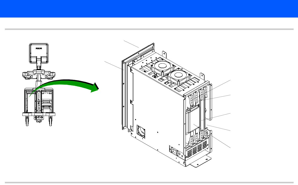
Figure 13-1 HD3 Primary System PCB Names and Locations (E-box)
Transducer Connector assy
Backplane
FE assembly
See Figure 13-11
BF board
See Figure 13-12
DSC board
See Figure 13-13
PCC board
See Figure 13-14
BFC connector
See Figure 13-10
See Figure 13-8
See Figure 13-9


