4535 612 34161 HD3 Service Manual Page 241
CSIP Level 1 Cabling: System Connector Illustrations
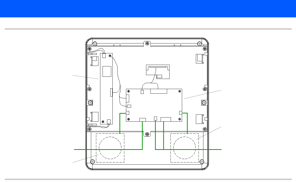
Figure 11-8 HD3 Video Monitor PCB Cable Connector Locations
CN3
CN1
CN2
GP2 J8
J10
GP3
J12
J9
J7
GP1
J11
Monitor power cable
(Connects to Control
Module Splitter board J1)
Monitor signal cable
(Connects to Control
Module Splitter board J2)
Left speaker
Right speaker
See Figure 13-5
See Figure 13-5


