4535 612 34161 HD3 Service Manual Page 197
CSIP Level 2 Disassembly: Disassembly (Removal) Procedures
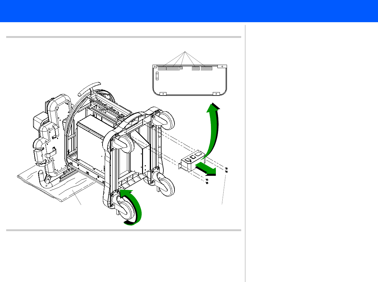
Figure 10-43 Removing the Power I/O Box
Panhead screws
(4 plcs)
8
9
10
Cable connections
Power I/O
box
7
7
7. Place a soft material protector pad
on the floor and carefully rotate the
system over on its front casters so
that the control panel handle rests
on the protector pad.
8. Remove the four screws securing the
Power I/O box to the cart frame.
9. Pull the Power I/O box away from
the underside of the system.
10. Disconnect all five power cable con-
nections from the backside of the
Power I/O box PCB.
Return to Disassembly Procedure List (2
of 2).


