


4535 612 34161 HD3 Service Manual Page 193
CSIP Level 2 Disassembly: Disassembly (Removal) Procedures
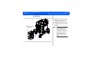
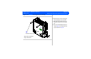
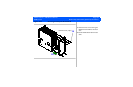
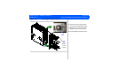
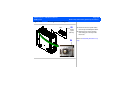
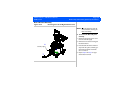
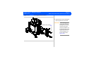
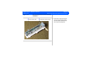
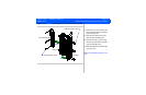
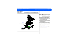
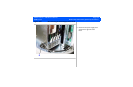
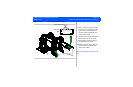
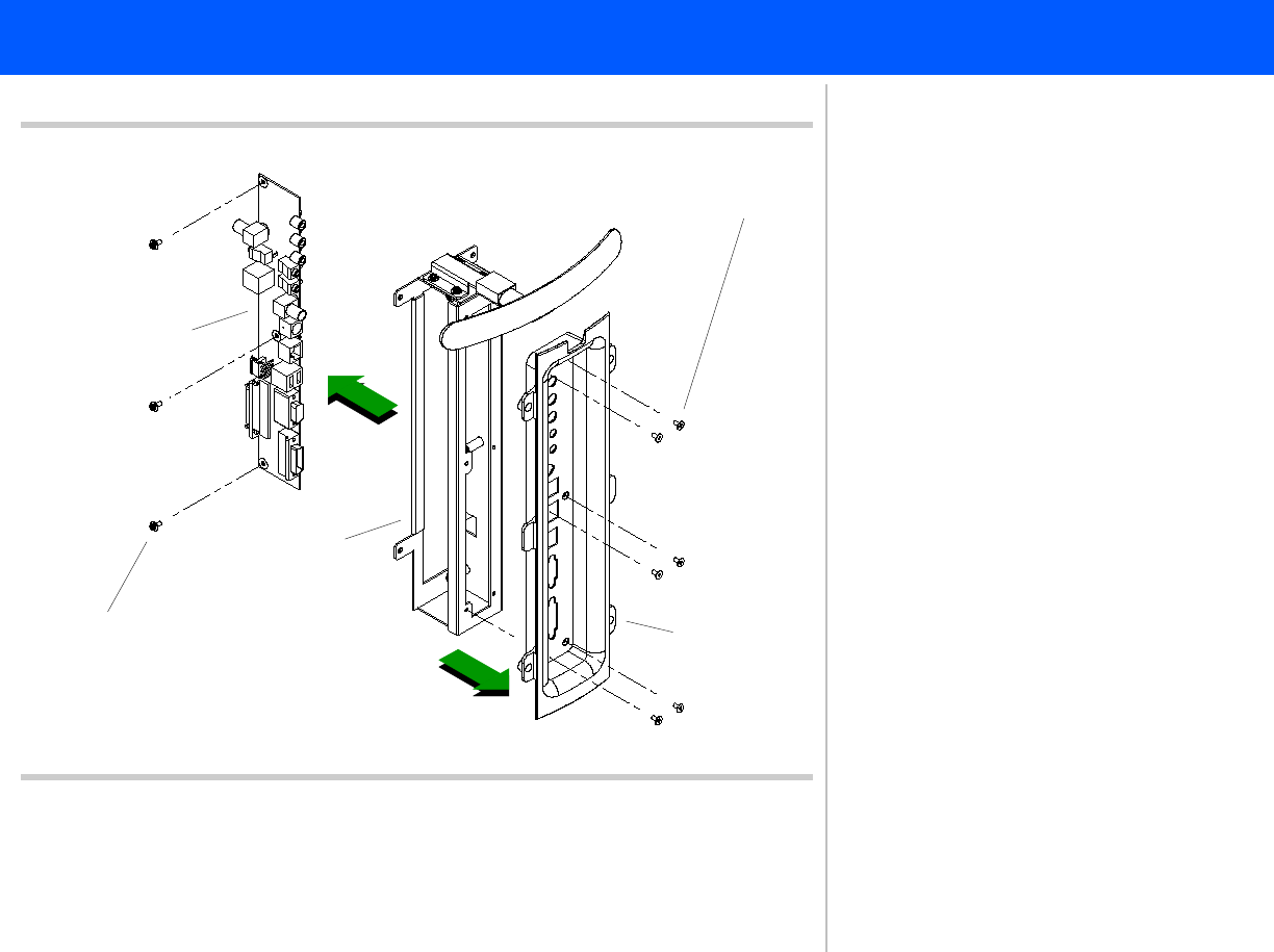
Figure 10-39 Removing the Rear I/O Panel Assembly PCB
Flathead screws (6 plcs)
7
8
Panhead screws (3 plcs)
9
10
Bezel
Rear I/O PCB
Frame
7. Remove the six screws securing the
Rear I/O panel bezel to the Rear I/O
panel assembly frame.
8. Slide the bezel off the front of the
Rear I/O panel assembly frame.
9. Remove the three screws securing
the Rear I/O panel PCB to the Rear
I/O panel assembly frame.
10. Slide the PCB out the backside open-
ing of the frame.
Return to Disassembly Procedure List (2
of 2).