


4535 612 34161 HD3 Service Manual Page 225
CSIP Level 1 Cabling: Introduction
11 Cabling
Introduction
This section contains system cabling and connector information. Use the illustrations (figures)
and parts tables in this section to locate and identify system cables and their part numbers. Part
numbers are shown on the illustrations and are listed and described in the corresponding tables.
NOTE Cable part numbers are located on at least one end of the cables.
System
Cabling
Diagrams
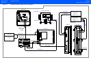
System signal interconnect and power distribution cabling diagrams are shown in Figure 11-1 and
Figure 11-2. For reference, system-to-peripheral connection diagrams are provided in
Figure 11-1 through Figure 11-3.
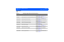
Cable Part
Numbers
Table 11-1 is a parts list of the interconnect cables shown in Figure 11-1 and the power distribu-
tion cables shown in Figure 11-2. Refer to Table 14-2 for additional information on peripherals
and applicable cables.
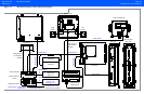
System
Connectors
Figure 11-4 through Figure 11-11 are illustrations of the system primary connector assemblies.