


4535 612 34161 HD3 Service Manual Page 63
CSIP Level 1 Theory of Operation: Functional Description
Tr a ns d uc e r
Connector
Assembly (TCA)
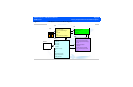
The Transducer Connector Assembly (TCA) is the transducer select module, providing the sys-
tem interface for two transducers (see Section 15, “Transducer Information”). It works with the
FE Board for transducer detection and identification, engaging the appropriate number of relays
to accommodate transmitting and receiving pulses and echoes.
Front End (FE)
Board
The Front End Board provides the physical and electrical interface to the TCA, the transducer
identification and enable function, and downloads operational parameters from the PCC, provid-
ing real-time control of the transmit, receive, and beamforming functions.
Beamformer
(BF)
The Beamformer Board is responsible for generating and transmitting pulses for the transducer
elements. When the returning echoes come back into the system, they are sent in analog form
through the FE to the Beamformer (via the Beamformer Connector Board that bridges and
interconnects the FE and the BF boards) for processing, where they are filtered prior to being
converted into digital data. Once the data is digitized, specialized circuits perform the beam
forming and steering.
The signal processing functions of digital beamforming that determine the real image quality of
the system include dynamic apodization, multiplication, coefficient loading, variable sample clock
generation, and dynamic gain control.
Digital Scan
Converter
(DSC)
The DSC Board is multi-functional, performing functions supported by separate circuit boards in
larger systems. The DSC performs the functions of a digital signal processor, digital scan con-
verter and real time clock, and video manager.
• DSP functions:
- Receives all signals from BF board
- Calculates blood velocity and direction