


4535 612 34161 HD3 Service Manual Page 129
CSIP Level 1 Performance Tests: Electrical Safety
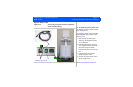
➤ To test the system for resistance between chassis and ground
1. Inspect the power cord for cracks and wear.
2. Set the mode on the analyzer to measure resistance in the power cord.
3. Plug the analyzer into an available AC wall outlet. Plug the ultrasound system power plug into
the test receptacle on the analyzer.
4. Make the appropriate connections between the analyzer and the ground lug on the ultra-
sound system’s I/O panel.
5. Read chassis ground resistance in milliohms. Flex the ultrasound power cord during the test
to detect intermittent changes in resistance value.
6. Record the highest resistance value measured in step 5. Check that the highest resistance
value is within the limit specified in Figure 6-1. If the reading exceeds the specified limit,
check the power cord and the associated primary wiring.
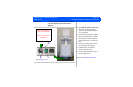
A comprehensive ground impedance measurement can be performed using the safety analyzer.
The impedance test drives a load current through the ground wire while measuring the AC volt-
age drop across the entire length of the power cord and to the system chassis. The reading will
be in milliohms.
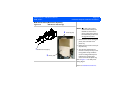
Ground Wire
Leakage
Current Test
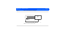
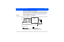
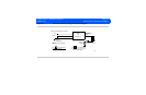
This test checks the entire system for leakage on chassis ground wires. Figure 6-2 shows the
basic electrical concept of the test. Use a safety analyzer and complete “To test the system
ground wiring for leakage” on page 131.
WARNING This test can be hazardous. Avoid any contact with line voltage. Any time during the test that the
ground connection is open, do not touch the chassis or the patient cable.