


Configure Flow Switch parameters
ProLink II • ProLink > Configuration > Flow > Flow Switch Setpoint
• ProLink > Configuration > Flow > Flow Switch Variable
• ProLink > Configuration > Flow > Flow Switch Hysteresis
ProLink III Device Tools > Configuration > I/O > Outputs > Discrete Output
Field Communicator • Configure > Manual Setup > Inputs/Outputs > Discrete Output > Flow Switch Source
• Configure > Manual Setup > Inputs/Outputs > Discrete Output > Flow Switch Setpoint
• Configure > Manual Setup > Inputs/Outputs > Discrete Output > Hysteresis
Overview
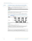
Flow Switch is used to indicate that the flow rate (measured by the configured flow variable)
has moved past the configured setpoint, in either direction. The flow switch is
implemented with a user-configurable hysteresis.
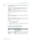
Procedure
1.
Set Discrete Output Source to Flow Switch, if you have not already done so.
2. Set Flow Switch Variable to the flow variable that you want to use to control the flow
switch.
3. Set Flow Switch Setpoint to the value at which the flow switch will be triggered (after
Hysteresis is applied).
• If the flow rate is below this value, the discrete output is ON.
• If the flow rate is above this value, the discrete output is OFF.
4. Set Hysteresis to the percentage of variation above and below the setpoint that will
operate as a deadband.
Hysteresis defines a range around the setpoint within which the flow switch will not
change. The default is 5%. The valid range is 0.1% to 10%.
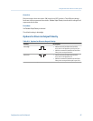
Example: If Flow Switch Setpoint = 100 g/sec and Hysteresis = 5%, and the first measured
flow rate is above 100 g/sec, the discrete output is OFF. It will remain OFF unless the
flow rate drops below 95 g/sec. If this happens, the discrete output will turn ON, and
remain ON until the flow rate rises above 105 g/sec. At this point it turns OFF and
will remain OFF until the flow rate drops below 95 g/sec.
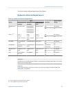
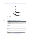
6.4.2 Configure Discrete Output Polarity
ProLink II ProLink > Configuration > Frequency/Discrete Output > Discrete Output > DO Polarity
ProLink III Device Tools > Configuration > I/O > Outputs > Discrete Output
Field Communicator Configure > Manual Setup > Inputs/Outputs > Discrete Output > DO Polarity
Integrate the meter with the control system
86 Micro Motion
®
Model 1500 Transmitters with Analog Outputs