


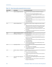
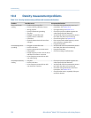

Frequency output problems and recommended actionsTable 10-7:
Problem Possible causes Recommended actions
No frequency output • Stopped totalizer
• Process condition below cutoff
• Fault condition if fault action is set to in-
ternal zero or downscale
• Slug flow
• Flow in reverse direction from config-
ured flow direction parameter
• Bad frequency receiving device
• Output level not compatible with receiv-
ing device
• Bad output circuit
• Incorrect internal/external power con-
figuration
• Incorrect pulse width configuration
• Output not powered
• Wiring problem
• Verify that the process conditions are below
the low-flow cutoff. Reconfigure the low-flow
cutoff if necessary.
• Check the Fault Action settings. See
Section 10.19.
• Verify that the totalizers are not stopped. A
stopped totalizer will cause the frequency
output to be locked.
• Check for slug flow. See Section 10.25.
• Check flow direction. See Section 10.23.
• Verify that the receiving device, and the wir-
ing between the transmitter and the receiv-
ing device.
• Verify that the channel is wired and config-
ured as a frequency output.
• Verify the power configuration for the fre-
quency output (internal vs. external).
• Check the pulse width. See Section 10.20.
• Perform a loop test. See Section 10.12.
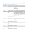
Consistently incorrect
frequency measure-
ment
• Output not scaled correctly
• Incorrect flow measurement unit config-
ured
• Check the frequency output scaling. See
Section 10.21.
• Verify that the measurement units are con-
figured correctly for your application.
Erratic frequency out-
put
• Radio frequency interference (RFI) from
environment
• Check for radio frequency interference. See
Section 10.13.
10.8 Use sensor simulation for troubleshooting
When sensor simulation is enabled, the transmitter reports user-specified values for mass
flow, temperature, and density. This allows you to reproduce various process conditions or
to test the system.
You can use sensor simulation to help distinguish between legitimate process noise and
externally caused variation. For example, consider a receiving device that reports an
unexpectedly erratic flow value. If sensor simulation is enabled and the observed flow rate
does not match the simulated value, the source of the problem is likely to be somewhere
between the transmitter and the receiving device.
Important
When sensor simulation is active, the simulated value is used in all transmitter outputs and
calculations, including totals and inventories, volume flow calculations, and concentration
calculations. Disable all automatic functions related to the transmitter outputs and place the loop in
manual operation. Do not enable simulation mode unless your application can tolerate these effects,
and be sure to disable simulation mode when you have finished testing.
Troubleshooting
162 Micro Motion
®
Model 1500 Transmitters with Analog Outputs