


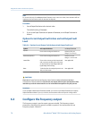
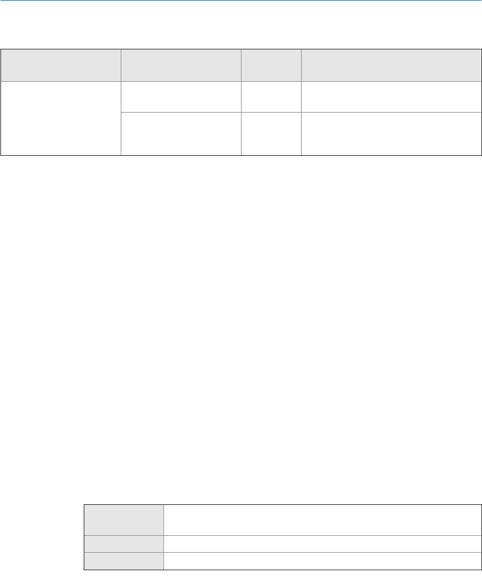
Valid values for Added Damping (continued)Table 6-3:
Setting of Update Rate
Process variable
Update rate
in effect
Valid values for Added Damping
Special
100 Hz variable (if assigned
to the mA output)
100 Hz 0.0, 0.04, 0.12, 0.30, 0.64, 1.32, 2.6, 5.4, 11, 22,
44, 88, 176, 350
100 Hz variable (if not as-
signed to the mA output)
All other process variables
6.25 Hz 0.0, 0.32, 0.96, 2.40, 5.12, 10.56, 20.8, 43.2, 88,
176, 352
Interaction between Added Damping and process variable
damping
When mA Output Process Variable is set to a flow variable, density, or temperature, Added
Damping interacts with Flow Damping, Density Damping, or Temperature Damping. If multiple
damping parameters are applicable, the effect of damping the process variable is
calculated first, and the added damping calculation is applied to the result of that
calculation.
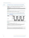
Example: Damping interaction
Configuration:
• Flow Damping = 1 second
• mA Output Process Variable = Mass Flow Rate
• Added Damping = 2 seconds
Result: A change in the mass flow rate will be reflected in the mA output over a time period
that is greater than 3 seconds. The exact time period is calculated by the transmitter
according to internal algorithms which are not configurable.
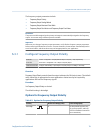
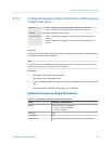
6.2.5 Configure mA Output Fault Action and mA Output Fault
Level
ProLink II • ProLink > Configuration > Analog Output > Primary Output > AO Fault Action
• ProLink > Configuration > Analog Output > Primary Output > AO Fault Level
ProLink III Device Tools > Configuration > Fault Processing
Field Communicator Configure > Manual Setup > Inputs/Outputs > mA Output > mA Fault Settings
Overview
mA Output Fault Action controls the behavior of the mA output if the transmitter encounters
an internal fault condition.
Integrate the meter with the control system
Configuration and Use Manual 77