


Procedure
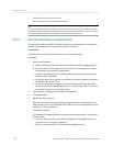
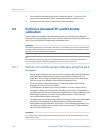
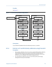
See Figure 9‐1.
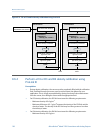
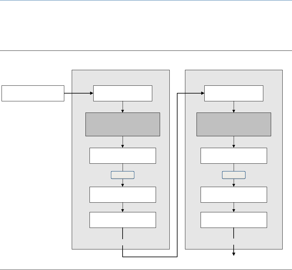
D1 and D2 density calibration using ProLink IIFigure 9-1:
Enter density of D1 fluid
Calibration in Progress
light turns green
Calibration in Progress
light turns red
D1 calibration
Close shutoff valve
downstream from sensor
Fill sensor with D1 fluid Fill sensor with D2 fluid
Close
Enter density of D2 fluid
Calibration in Progress
light turns green
Calibration in Progress
light turns red
D2 calibration
Close
Done
Do Cal Do Cal
ProLink Menu >
Calibration >
Density cal – Point 1
ProLink Menu >
Calibration >
Density cal – Point 2
Postrequisites
If you disabled LD Optimization before the calibration procedure, re-enable it.
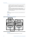
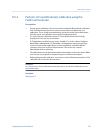
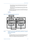
9.5.2 Perform a D1 and D2 density calibration using ProLink III
Prerequisites
• During density calibration, the sensor must be completely filled with the calibration
fluid, and flow through the sensor must be at the lowest rate allowed by your
application. This is usually accomplished by closing the shutoff valve downstream
from the sensor, then filling the sensor with the appropriate fluid.
• D1 and D2 density calibration require a D1 (low-density) fluid and a D2 (high-
density) fluid. You may use air and water.
Measurement support
Configuration and Use Manual 131