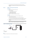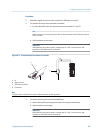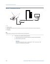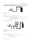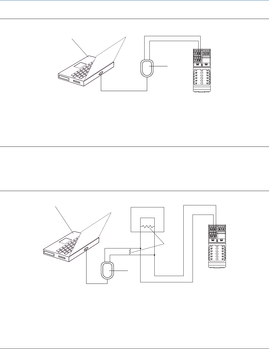
Connection to transmitter terminalsFigure B-5:
A
B
C
A. PC
B.
Signal converter
C. Transmitter
Note
This figure shows a serial port connection. USB connections are also supported.
3. To connect over the RS-485 network:
a.
Attach the leads from the signal converter to any point on the network.
b. Add resistance as necessary.
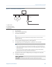
Connection over networkFigure B-6:
D
C
A
B
E
A. PC
B.
Signal converter
C.
120-
Ω
, 1/2‐watt resistors at both ends of the segment, if necessary
D. DCS or PLC
E. Transmitter
Note
This figure shows a serial port connection. USB connections are also supported.
4. Start ProLink III.
5.
Choose Connect to Physical Device.
Using ProLink III with the transmitter
Configuration and Use Manual 207


