


- Terminate the shielding at the output device. If this is impossible, terminate the
shielding at the cable gland or conduit fitting.
- Do not terminate the shielding inside the wiring compartment.
- 360-degree termination of shielding is unnecessary.
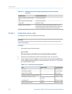
10.14 Check the HART communication loop
If you cannot establish or maintain HART communications, the HART loop may be wired
incorrectly.
Prerequisites
You will need:
• A copy of your transmitter installation manual
• A Field Communicator
• Optional: the HART Application Guide, available at www.hartcomm.org
Procedure
1. Verify that the loop wires are connected as shown in the wiring diagrams in the
transmitter installation manual.
If your HART network is more complex than the wiring diagrams in the transmitter
installation manual, contact either Micro Motion or the HART Communication
Foundation.
2. Disconnect the primary mA output wiring from the transmitter.
3. Install a 250–1000 Ω resistor across the transmitter’s primary mA output terminals.
4. Check the voltage drop across the resistor (4–20 mA = 1–5 VDC).
If voltage drop is less than 1 VDC, add resistance to achieve a voltage drop of greater
than 1 VDC.
5. Connect a Field Communicator directly across the resistor and attempt to
communicate (poll).
If communication with the transmitter cannot be established, the transmitter may
need service. Contact Micro Motion.
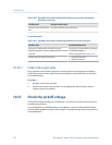
10.15 Check HART Address and Loop Current Mode
If the transmitter is producing a fixed current from the mA output, the Loop Current Mode
parameter may be disabled.
When Loop Current Mode is disabled, the mA output produces a fixed value, and does not
report process data or implement its fault action.
Troubleshooting
Configuration and Use Manual 169