


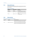

Status alarms and recommended actions (continued)Table 10-2:
Alarm code Description Recommended actions
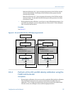
A003 No Sensor Response The transmitter is not receiving one or more basic electrical sig-
nals from the sensor. This could mean that the wiring between
the sensor and the transmitter has been damaged, or that the
sensor requires factory service.
1.
Check the drive gain and pickoff voltage. (See Section 10.26
and Section 10.27.)
2. Check the wiring between the sensor and the transmitter.
a. Using the installation manual for your transmitter, verify
that the transmitter is connected to the sensor according
to the instructions. Obey all safety messages when open-
ing wiring compartments.
b. Verify that the wires are making good contact with the
terminals.
c. Perform RTD resistance checks and check for shorts to
case (see Section 10.28.1).
d. Check the continuity of all wires from the transmitter to
the sensor.
3. Check for electrical shorts. See Section 10.28.
4. Check the integrity of the sensor tubes.
A004 Temperature Overrange The sensor RTD is signaling a resistance that is out of range for
the sensor.
1.
Check the sensor RTD resistance values and for RTD shorts to
case. (See Section 10.28.1.)
2. Check the wiring between the sensor and the transmitter.
a. Using the installation manual for your transmitter, verify
that the transmitter is connected to the sensor according
to the instructions. Obey all safety messages when open-
ing wiring compartments.
b. Verify that the wires are making good contact with the
terminals.
c. Perform RTD resistance checks and check for shorts to
case (see Section 10.28.1).
d. Check the continuity of all wires from the transmitter to
the sensor.
3. Verify temperature characterization parameters (Temp Cal
Factor).
4. Check your process conditions against the values reported
by the flowmeter.
Troubleshooting
Configuration and Use Manual 145