


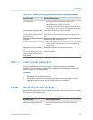

Standard core processor LED states (continued)Table 10-13:
LED state Description Recommended actions
Core processor internal failure The meter requires factory service.
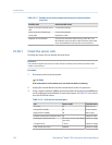
Enhanced core processor LED statesTable 10-14:
LED state Description Recommended action
Solid green Normal operation No action required.
Flashing yellow Zero in progress No action required.
Solid yellow Low-severity alarm Check alarm status.
Solid red High-severity alarm Check alarm status.
Flashing red (80% on, 20% off) Tubes not full • If alarm A105 (slug flow) is active, refer to the
recommended actions for that alarm.
• If alarm A033 (tubes not full) is active, verify
process. Check for air in the flow tubes, tubes
not filled, foreign material in tubes, or coating
in tubes.
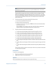
Flashing red (50% on, 50% off) Electronics failed The meter requires factory service.
Flashing red (50% on, 50% off,
skips every 4th)
Sensor failed The meter requires factory service.
OFF Core processor receiving less
than 5 volts
• Verify power supply wiring to core processor.
• If transmitter status LED is lit, transmitter is re-
ceiving power. Check voltage across terminals
1 (VDC+) and 2 (VDC–) in core processor. If
reading is less than 1 VDC, verify power supply
wiring to core processor. Wires may be switch-
ed.
• If transmitter status LED is not lit, transmitter
is not receiving power. Check power supply. If
power supply is operational, internal transmit-
ter, display, or LED failure is possible – the me-
ter may require factory service.
Core processor internal failure The meter requires factory service.
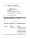
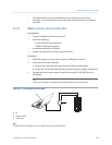
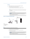
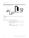
10.30 Perform a core processor resistance test
1. Power down the transmitter.
2. Remove the core processor lid.
3. At the core processor, disconnect the 4-wire cable between the core processor and
the transmitter.
4. Measure the resistance between core processor terminal pairs 3–4, 2–3, and 2–4.
Troubleshooting
Configuration and Use Manual 179