


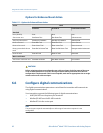
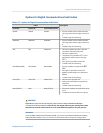


Options for Digital Communications Fault Action
Options for Digital Communications Fault ActionTable 6-15:
Label Description
ProLink II ProLink III Field Communicator
Upscale Upscale Upscale
• Process variable values indicate that the
value is greater than the upper sensor lim-
it.
• Totalizers stop incrementing.
Downscale Downscale Downscale
• Process variable values indicate that the
value is greater than the upper sensor lim-
it.
• Totalizers stop incrementing.
Zero Zero IntZero-All 0
• Flow rate variables go to the value that
represents a flow rate of 0 (zero).
•
Density is reported as 0.
•
Temperature is reported as 0 °C, or the
equivalent if other units are used (e.g.,
32 °F).
• Drive gain is reported as measured.
• Totalizers stop incrementing.
Not-a-Number (NAN) Not a Number Not-a-Number
•
Process variables are reported as IEEE
NAN.
• Drive gain is reported as measured.
• Modbus scaled integers are reported as
Max Int.
• Totalizers stop incrementing.
Flow to Zero Flow to Zero IntZero-Flow 0
•
Flow rates are reported as 0.
• Other process variables are reported as
measured.
• Totalizers stop incrementing.
None (default)
None
None (default) • All process variables are reported as meas-
ured.
• Totalizers increment if they are running.
CAUTION!
If you set mA Output Fault Action or Frequency Output Fault Action to None, be sure to set Digital
Communications Fault Action to None. If you do not, the output will not report actual process data,
and this may result in measurement errors or unintended consequences for your process.
Restriction
If you set Digital Communications Fault Action to NAN, you cannot set mA Output Fault Action or Frequency
Output Fault Action to None. If you try to do this, the transmitter will not accept the configuration.
Integrate the meter with the control system
Configuration and Use Manual 99