


Fault Timeout
configuring 62
effect on Fault Action 62
Field Communicator
connecting to the transmitter 218
device description (DD) 217
menu maps 220
overview 217, 218
startup connection 8
Floating-Point Byte Order 96
flow damping
configuring 26
effect on volume measurement 27
interaction with added damping 27
flow direction
troubleshooting 172
Flow Direction
configuring 39
effect on digital communications 43
effect on discrete outputs 43
effect on frequency outputs 43
effect on mA outputs 40
effect on totalizers and inventories 44
options 39
flow factor, See pressure compensation
flow switch 86
Frequency Factor 80
frequency outputs
configuring 78
Fault Action
configuring 83
options 83
loop testing
using ProLink II 164
using ProLink III 166
using the Field Communicator 167
maximum pulse width 82
polarity
configuring 79
options 79
scaling method
configuring 80
Frequency = Flow 80
troubleshooting 161, 171
G
gas standard volume flow measurement
configuring 33
cutoff
configuring 37
interaction with AO cutoff 38
effect of flow damping on 27
effect of mass flow cutoff on 28
measurement units
configuring 35
options 35
standard density 34
volume flow type 34
grounding
troubleshooting 164
GSV, See gas standard volume flow measurement
H
HART
address 93, 169
burst mode 94, 170
device description (DD) 217
HART/Bell 202
configuring 93
Field Communicator connections 218
loop 169
Loop Current Mode 93, 169
variables
configuring 95
interaction with transmitter outputs 96
options 95
hysteresis 86
I
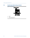
I/O terminals 244
informational parameters 66
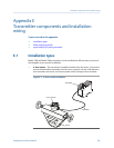
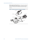
installation types
4-wire remote 241
9-wire remote 241
high-temperature flexible conduit 241
integral 241
remote core processor with remote transmitter 241
inventories
resetting 113
starting and stopping 112
L
Last Measured Value Timeout, See Fault Timeout
LD Optimization 130, 131, 133
LED, See status LED
Loop Current Mode 93, 169
loop testing
using ProLink II 164
using ProLink III 166
using the Field Communicator 167
Lower Range Value (LRV) 73
Index
Configuration and Use Manual 251