


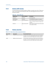
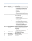

Status alarms and recommended actions (continued)Table 10-2:
Alarm code Description Recommended actions
A010 Calibration Failure This alarm is typically caused by flow through the sensor during
the zero, or by a zero offset result that is out of range. Power to
the transmitter must be cycled to clear this alarm.
1.
Cycle power to the meter.
2. Make sure there is no flow through the sensor.
3. Retry the zero calibration.
4. Power-cycle the transmitter.
A011 Zero Calibration Failed: Low This alarm is caused by reverse flow in the sensor during the
zero, or by a zero offset result that is below the valid range. This
alarm will be accompanied by A010. Power to the transmitter
must be cycled to clear this alarm.
1.
Cycle power to the meter.
2. Make sure there is no flow through the sensor.
3. Retry the zero calibration.
4. Power-cycle the transmitter.
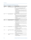
A012 Zero Calibration Failed: High This alarm is caused by positive flow in the sensor during the
zero, or by a zero offset result that is above the valid range. This
alarm will be accompanied by A010. Power to the transmitter
must be cycled to clear this alarm.
1.
Cycle power to the meter.
2. Make sure there is no flow through the sensor.
3. Retry the zero calibration.
4. Power-cycle the transmitter.
A013 Zero Calibration Failed: Unsta-
ble
There was too much instability during the calibration procedure.
Power to the transmitter must be cycled to clear this alarm.
1.
Remove or reduce sources of electromechanical noise (e.g.,
pumps, vibration, pipe stress).
• Check the drive gain and pickoff voltages to confirm that
the sensor is in a stable state.
• Retry the procedure.
2. Cycle power to the meter, then retry the procedure.
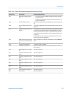
A014 Transmitter Failure 1. Check that all wiring compartment covers are installed prop-
erly.
2.
Check that the wiring connected to the transmitter meets
specifications and that all cable shields are properly termina-
ted.
3. Check that the sensor and transmitter are both grounded
properly.
4. Evaluate the environment for sources of high electromag-
netic interference (EMI) and relocate the transmitter or wir-
ing as necessary.
Troubleshooting
148 Micro Motion
®
Model 1500 Transmitters with Analog Outputs